Speed Cracks in Aluminium Extrusion: Causes and Prevention
Speed cracks are a characteristic surface defect in aluminium extrusion. They usually appear as a series of fine cracks oriented predominantly transverse to the extrusion direction.
The name itself points to one of the main causes: extrusion speed.
However, speed alone does not determine whether cracking will occur. Alloy composition, metal temperature, profile geometry, die design and billet condition all influence the maximum practical extrusion speed.
This is why a profile that runs successfully in 6060 or 6063 may begin to crack when produced in a higher-strength alloy such as 6005A, 6061 or 6082.
What Do Speed Cracks Look Like?
Speed cracks usually appear as repeated surface cracks oriented predominantly transverse to the extrusion direction.
They may be very fine and shallow at the beginning. As extrusion conditions become more severe, the cracks can become more pronounced and occur at shorter intervals.
The defect is normally associated with the surface of the profile rather than with internal cracking of the entire section.
This orientation is useful when diagnosing the defect. Longitudinal lines or scratches are more likely to indicate other problems, such as die lines, handling damage or surface pick-up.
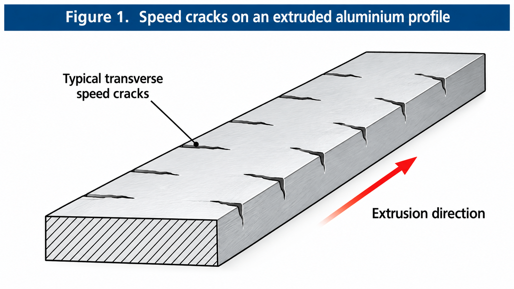 Figure 1. Typical speed cracks on an aluminium extrusion. The cracks are predominantly transverse to the extrusion direction.
Why Do Speed Cracks Form?
Speed cracks form when the surface of the extruded metal can no longer withstand the combination of temperature, deformation and stress imposed during high-speed extrusion.
As extrusion speed increases, deformation and frictional heating raise the temperature of the metal, particularly near the surface and die bearing.
If the local exit temperature approaches a critical temperature for the alloy, the surface metal may lose sufficient hot ductility to withstand the stresses imposed at the die exit. In higher-alloyed 6xxx alloys, this critical condition may be associated with incipient melting of low-melting constituent phases.
At the same time, the stress state at the edge of the die bearing is important. Local tensile stress can promote initiation of surface tearing when the metal is already in a critical thermal condition. Recent experimental and numerical work on a high-strength AA6082 alloy confirms the importance of this interaction between temperature and stress at the die bearing. DOI
The resulting defects typically appear as a series of cracks oriented predominantly transverse to the extrusion direction.
An important practical point follows:
Speed cracks originate at the die exit. They are not caused by the downstream quench.
By the time the profile reaches intensive cooling farther along the run-out table, the surface cracks may already have formed.
Why Alloy Matters
The tendency to speed cracking differs considerably among 6xxx aluminium alloys.
Relatively low-alloyed extrusion alloys such as 6060 and 6063 generally have good hot workability and a relatively wide extrusion process window. Published work comparing extrudability also identifies 6063 as having a substantially wider processing window than more highly alloyed materials.
Higher-strength 6xxx alloys such as 6005A, 6061 and 6082 normally require more conservative extrusion conditions.
This does not mean that 6060 or 6063 cannot develop speed cracks. They certainly can if the extrusion conditions become sufficiently severe.
The important difference is relative susceptibility.
Under comparable extrusion conditions, higher-strength 6xxx alloys generally reach the speed-cracking limit earlier than 6060 or 6063.
Consequently, an extrusion speed that is acceptable for a 6060 profile may be excessive for a similar profile in 6082.
There Is No Universal Maximum Extrusion Speed
It is tempting to specify one maximum exit speed for each alloy.
In practice, this is rarely useful.
The allowable speed depends on billet and die temperatures, extrusion ratio, profile geometry and wall thickness, die design and bearing conditions, metal-flow distribution, press conditions and actual exit temperature.
A simple solid profile and a complicated thin-wall hollow profile made from the same alloy may therefore have very different practical speed limits.
The useful concept is not a single maximum speed but a safe extrusion window.
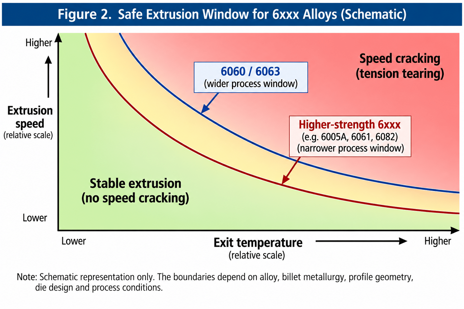 Figure 2. Schematic safe extrusion window for 6xxx alloys. Higher-strength alloys such as 6005A, 6061 and 6082 generally reach the speed-cracking limit at lower combinations of extrusion speed and exit temperature than 6060/6063. Actual limits depend on alloy, billet metallurgy, profile geometry,
die design and process conditions.
The boundaries in Figure 2 are intentionally shown without numerical temperature or speed values. They should not be interpreted as universal operating limits.
Exit Temperature Is Critical
Billet temperature alone does not describe the thermal condition of the extrusion.
During extrusion, severe plastic deformation generates heat. Friction and deformation in the die and bearing region further affect the surface temperature.
The metal can therefore leave the die considerably hotter than the billet was before extrusion.
Increasing extrusion speed can consequently increase both deformation rate and exit temperature. This helps explain why speed cracking can appear rather suddenly as production speed is increased.
Experiments on AA6082 show this clearly: at constant extrusion conditions, surface quality deteriorated from the front towards the middle and back of an extrusion as temperature increased. Increasing extrusion speed also produced progressively larger surface cracks. DOI
For this reason, exit-temperature measurement is particularly useful when optimizing extrusion speed.
Profile Geometry and Die Design
Alloy and temperature are not the only factors.
Different parts of a profile do not necessarily experience identical metal flow, deformation or thermal conditions. Thin walls, changes in section thickness and difficult metal-flow paths can create local conditions more severe than those suggested by average extrusion speed.
Die design and bearing geometry can therefore influence where and when speed cracks appear.
This effect can be substantial. In recent AA6082 trials, choked bearings allowed higher extrusion speeds without visible surface cracking than flat or zero-bearing configurations. Numerical modelling showed that the choke changed the stress state near the die corner, reducing tensile stress or even producing compression. DOI
If cracking repeatedly occurs in one particular region of a profile while the remainder of the surface is acceptable, simply reducing speed may suppress the symptom but may not identify the whole cause. Local metal flow and bearing conditions should also be examined.
How to Diagnose Speed Cracking
The simplest diagnostic test is often operational.
If transverse surface cracking appears at high extrusion speed and disappears when speed is reduced, speed cracking should be strongly suspected.
The diagnosis becomes more convincing when several observations agree: the cracks are predominantly transverse to the extrusion direction; severity increases with extrusion speed and exit temperature; the defect becomes more pronounced in less-extrudable alloys; and reducing thermal or deformation severity eliminates it.
However, not every transverse surface defect is automatically a speed crack. Die damage, billet defects, severe pick-up and other surface problems should also be excluded.
How to Prevent Speed Cracks
The first corrective action is normally simple:
Reduce extrusion speed.
But production optimization should not stop there.
If an unusually large speed reduction is required, billet and die temperatures, exit temperature, profile geometry, die condition and metal-flow balance should be examined systematically.
For higher-strength alloys such as 6005A, 6061 and 6082, realistic productivity expectations are especially important. Trying to run them under conditions suitable for readily extrudable 6060/6063 profiles can move the process outside its safe extrusion window.
The objective is therefore not the highest possible ram or exit speed.
It is the highest stable speed that maintains the required profile quality.
Conclusion
Speed cracking is controlled by the interaction between aluminium metallurgy and extrusion conditions.
High extrusion speed increases deformation rate and heat generation. As the surface temperature approaches a critical condition for the alloy, the metal becomes increasingly susceptible to tearing. The stress state at the die bearing then plays an important role in whether a surface crack actually initiates.
For readily extrudable alloys such as 6060 and 6063, the safe processing window is generally relatively wide. Higher-strength 6xxx alloys such as 6005A, 6061 and 6082 normally require more conservative conditions.
The practical lesson is simple:
Maximum extrusion speed is not a fixed property of an alloy. It is the result of the complete alloy–profile–die–temperature–speed system.
References
- Wang, X., Khan, M. S., Wells, M. A., Poole, W. J., Parson, N. Effect of Die Bearing Geometry on Extrudability of High-Strength AA6082 Alloy with Cu. Journal of Materials Engineering and Performance, 34, 24629–24644 (2025). Article and DOI
- Saha, P. K. Aluminum Extrusion Technology. ASM International, 2000.
- Sheppard, T. Extrusion of Aluminium Alloys. Kluwer Academic Publishers, 1999.