Extrusion press alignment
General principles of extrusion press alignment
Typical direct-action extrusion presses are shown in Figures 1-3.
 Fig. 1 – A typical direct extrusion press (Kennedy) [1, 2]
 Fig. 2 – Illustration of press components (Drawing courtesy of RL Best) [1]

1 – hydraulic power unit; 2 – tie rods; 3 – butt shear; 4 – extrusion platen;
5 – container shifting cylinders; 6 – operator’s console; 7 – die slide; 8 – container;
9 – container housing; 10 – billet loader; 11 – press base; 12 – billet loader cylinders;
13 – pressing stem; 14 – crosshead; 15 – side cylinders; 16 – cylinder platen;
17 – main cylinder
Fig. 3 – Typical direct drive hydraulic extrusion press [2]
Основные 3-х мерные геометрические соотношения между компонентами обычного пресса для экструзии алюминия сводятся к следующему ((Fig. 4 and 5).
The geometric relationships of the static components
- The press base should be level with respect to gravity. The relevant contact points should lie in a flat plane.
- The back platen and the front platen should be located perpendicular to the base.
- The pressure ring bushing should have its hole centered in the front platen. Its front surface should be flat and parallel to the front platen.
- The press center line is the line joining the platen centers, and all the platen-centered components should lie on this line.
- The guide ways for the crosshead and container should be straight and parallel to the base. They should be symmetrically spaced about the press center line.
- The main cylinder, bearing bushing, flange, and ram piston should be concentric and centerd on and perpendicular to the back platen.
- The crosshead should be center-mounted on the ram and fitted with a straight and centered extrusion stem perpendicular to the back platen.
- The geometric center lines of each of the four machined tie rods or columns should be parallel to and symmetrically located about the press center line.
The geometric relationships of the moving components
- The ram piston and the extrusion stem move along the press centerline over their full stroke.
- The center line of the container bore is coincident as it moves along the press center line from its open to closed position.
- The centerline of the tooling stack is coincident with the press center line loads.
- The billet loader positions the billet so that its centerline matches the centerline of the container and stem before it is loaded into the container.


Fig. 4 – The views of an extrusion press [1]
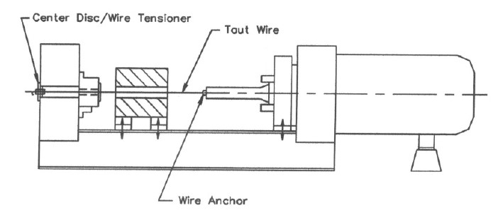 Fig.5 – The alignment of the moving components[1]
Источники:
1. Extrusion Press Maintenance Manual, ed. Al Kennedy
2. Aluminium and Aluminium Alloys /Ed. J.R. Davis – ASM Internatonal, 1993
3. Extrusion Press Alignment with Modern Technology / Joseph E.V. Mulder and Gavin J. Smith – Aluminum Extrusion Technology Seminar, 2000
