Direct aluminium extrusion
Discover the key steps and tools involved in direct aluminium extrusion. Learn how this process creates profiles with precise cross-sections.
An aluminium extrusion press
- Aluminium billet (cylindrical ingot) is heated and extruded through a die with one or more holes, to obtain a profile with a predetermined cross-section.
- The most common type of extrusin is direct extrusion (Figure 1).
- The most of the presses for this technology are horizontal and hydraulic (Figure 2).
- Capacity depends on the size press matrices used, which may have a diameter of 100 to 1000 mm.
- For the majority of extruded aluminum products used die diameter is 175 to 250 mm.
- For dies of such diameters are required extrusion presses with a force of 1500 to 2000 tonnes.
All details about aluminium extrusion presses:
Extrusion Press Maintenance Manual / Al Kennedy
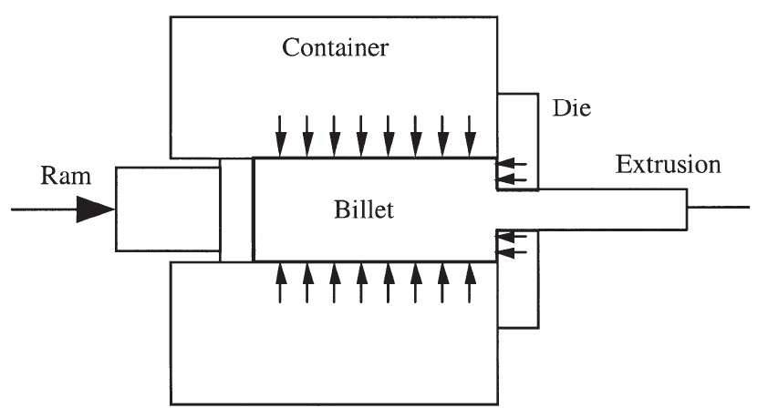 Figure 1 – Direst aluminium extrusion [1]

1 – ram; 2 – dummy block; 3 – container; 4 – feeder plate; 5 – die; 6 – backer;
7 – bolster; 8 – die holder; 9 – die holder carrer
Figure 2 – Direct aluminium extrusion press tools [2]
The ram (1) is fitted with a steel dummy block (2) that fits tightly into the container (3) and prevents aluminium (shown in black) from leaking backwards. The die (5) is part of a die assembly or tool stack, made out of tool steel. The backer (6), bolster (7) and the die holder (8) and its carrier (9) are supporting the die under the extrusion load. A feeder plate (4) may be used before the die to spread out the flow from the container to a larger area on the die. In direct extrusion no lubrication is used, so that the outer layer of the billet is sheared off by friction with the container wall [1].
Heating of aluminium billets
- To ease the deformation process and to minimise work hardening of metal, the aluminium billet is heated to about 400-500°C before it enters the press.
- The container and the die are also heated to prevent the billet from cooling down.
The types of extrusion dies
- The most widely used types of dies are flat dies and porthole dies.
- Flat dies consist of only one piece and can be used to extrude solid profiles (Figure 3a).
- Porthole dies are made up of two pieces, a plate and a mandrel.
- This allows the extrusion of hollow (figure 3b) and semi-hollow (figure 3c) profiles.
- Dies of either type may have multiple cavities, so that multiple instances of a profile can be extruded at once [1]

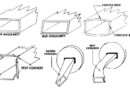
a – solid profile; b – hollow profile; c – semi-hollow profile
Figure 3 – Three types of extrusion profiles [2]
A flat extrusion die
A flat extrusion die is shown in figure 4. The most important features are the sink-in (1), which is an optional pocket, the bearing (2) and the die relief (3) [2].
- The bearing is the area that gives the aluminium its final shape. To minimise the required extrusion force the bearing does not extend over the entire die thickness, but has a length of 15 mm or less.
- The function of the die relief is to provide adequate support to the bearing without making contact with the aluminium. This means that it angles out at about 5 degrees and usually has some clearance just below the bearing.
- The sink-in’s function is to protect the fragile bearing when the back end of the billet is sheared off and to facilitate the transverse welding of one billet to the next [4]. Additionally it can be used as a means to control the flow of the aluminium.
 Figure 4 – A flat aluminium extrusion die [2]
A porthole aluminium extrusion die
Figure 5 shows a porthole die. As mentioned it consists of two parts, the plate (a) and the mandrel (b).
- The mandrel has one or more cores (1) with bearings that shape the inner contour(s) of the profile. The cores are attached to the rest of the mandrel through legs (2).
- The aluminium flows around these legs through feeder holes (3) and rejoins in the welding chamber (4).
- The final shape is then formed where the bearings of the mandrel and plate combine (5).

Figure 5 – A porthole aluminium extrusion die [2]
Controlling the aluminium flow
Controlling the flow using variable die bearing geometry. A method most commonly used by designers to achieve a uniform exit velocity in extrusion dies is the variation of the bearing geometry [1-4].
- Increasing the length of the bearing channel increases the resistance to flow and therefore decreases the exit velocity (Figure 6)
- When a positive angle is introduced the bearing is said to be ‘choked’ and with a negative angle it is ‘relieved’ (figure 7).
- Bearing angle variations are most commonly used in situations where only a bearing length variation cannot adequately correct the flow speed differences. This is the case when bearing length variations have such sudden transitions that marks will show up on the extruded profile [2].
- Bearing angle variations are also a popular means for correctors at extrusion plants to fine tune a die, because with only a small amount of material removal sections can be sped up or slowed down.
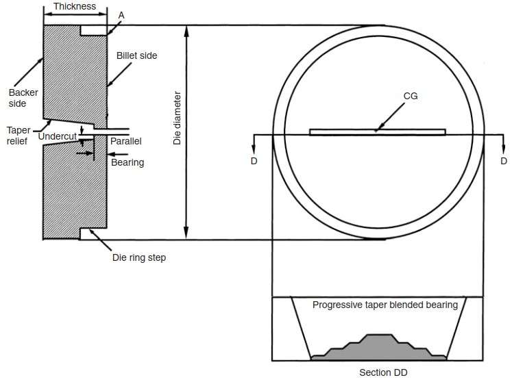 Figure 6 – Controlling metal flow through variable bearing length [1]
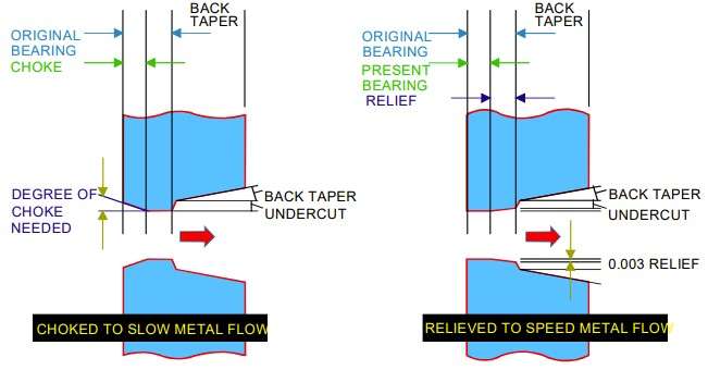 Figure 7 – Methods for slowing or speeding metal flow through an extrusion die [3]
Sources:
- Aluminium Extrusion Technology / P. Saha
- CAD Implentation of Design Rules for Aluminium Extrusion Dies / Gijs van Ouwerkerk, PhD Thesis, the University of Twente, Enschede, The Netherlands, 2009
- TALAT 1302
- Extrusion of Aluminium Alloys / T. Sheppard