Die Lines, Micro Die Lines and Pick-up in Aluminium Extrusion
Die Lines, Micro Die Lines and Pick-up are among the most common aluminium extrusion surface defects. They all tend to follow the extrusion direction, but they do not necessarily have the same cause.
A continuous line may be connected with a local irregularity of the die bearing. Very fine parallel lines may be Micro Die Lines. Intermittent rough marks, sometimes with a characteristic comet-like appearance, may indicate Pick-up.
Correct identification is important. Polishing the die, reducing extrusion speed or increasing etching time are not universal solutions. The first task is to understand where and how the surface defect was created.
This article focuses mainly on 6xxx-series extrusion alloys, especially alloys such as 6060 and 6063.
1. Die Lines
A Die Line is normally a distinct continuous longitudinal line running parallel to the extrusion direction. It usually remains in the same position relative to the profile cross-section.
The line can appear as either a groove or a ridge.
This is important because the geometry seen on the profile is opposite to the corresponding local geometry of the die bearing:
bearing depression → profile ridge
bearing projection or raised irregularity → profile groove
Possible causes include local bearing damage, wear, adhered aluminium, oxide or another hard particle, and incorrect die polishing or correction.
A hard particle at the bearing entrance may also damage the bearing and leave a local irregularity that then produces a continuous line on the extrudate.
The most useful diagnostic feature is position. If the same line appears in the same place on successive lengths produced from the same die, the corresponding area of the bearing should be inspected.
This distinguishes many Die Lines from handling scratches. A handling scratch is produced after the profile surface has left the die and may occur at different positions or angles.
A shallow Die Line may be reduced or even removed during E6 etching. A deeper one may remain visible. Therefore, the statement that Die Lines always remain after etching is too simple.
However, stronger etching should not be used routinely to compensate for poor extrusion surface quality.
2. Micro Die Lines
Micro Die Lines are much finer than conventional Die Lines. They normally appear as many closely spaced longitudinal features rather than one isolated groove or ridge.
They can be particularly easy to see under low-angle reflected light.
It is tempting to describe Micro Die Lines simply as miniature Die Lines produced by microscopic bearing roughness. Research on AA6063 shows that the mechanism is more complex.
Clode and Sheppard found that surface formation involves interaction between the extrudate and the die bearing. Even under favourable extrusion conditions, finer and shallower features remained. They called these microdie lines and related their origin to deformation and the nature of the shear zone.
Later work has also connected fine extrusion surface features with near-surface deformation and microstructural effects.
This gives a useful practical distinction:
one pronounced local continuous line → Die Line
many very fine parallel longitudinal features → Micro Die Lines
There is not necessarily a sharp physical boundary between the two categories.
Because Micro Die Lines are normally very shallow, E6 etching can substantially reduce their physical relief. In some cases, the original lines may no longer be visible after etching.
That does not mean that every longitudinal visual feature remaining after E6 is a Micro Die Line.
3. Pick-up
Pick-up is associated with local adhesion and material transfer at the die bearing.
A simplified sequence is:
local material transfer → build-up on bearing → growth → detachment → Pick-up marks on the extrudate
Research on AA6063 describes Pick-up as intermittent torn marks, often associated with a protruding lump of transferred material. Models of the phenomenon consider the initiation, growth and detachment of material accumulated on the bearing.
The surface appearance may resemble a comma, tear drop or comet.
The raised head should not be imagined as extending through the complete tail. The head is a compact local accumulation of material. Behind it, the tail is mainly a progressively decreasing surface disturbance.
This also helps explain why individual Pick-up marks may be separated by relatively long areas of apparently normal surface.
Pick-up does not necessarily become steadily worse during one die run. A possible sequence is:
good surface → build-up → increasing Pick-up → detachment → temporary improvement → new build-up
Therefore, Pick-up can have a variable or cyclic character.
Factors affecting Pick-up include bearing condition, adhesion, extrusion speed, billet and die temperature, extrudate surface temperature, local pressure and flow conditions, alloy and die geometry.
Simply cleaning the die may temporarily remove the symptom. If Pick-up repeatedly returns at the same location, the more useful question is:
Why does material transfer repeatedly occur at this particular part of the bearing?
4. How to Tell Them Apart
A practical examination can start with four questions:
- Is the mark continuous?
- Does it remain at the same transverse position?
- Is there evidence of local transferred or raised aluminium?
- Does its severity change during the die run?
A Die Line is normally continuous and remains at a fixed transverse position.
Micro Die Lines are also generally continuous, but appear as many very fine features over a wider surface area.
Pick-up is intermittent. However, individual Pick-up marks can repeatedly occur in approximately the same transverse position because they originate from the same region of the bearing. Therefore, fixed position alone does not distinguish Pick-up from a Die Line.
Magnification and low-angle lighting are useful. For difficult cases, surface profilometry can help determine whether the observed feature is true topography or mainly an optical difference.
Whenever possible, keep and inspect a mill-finish reference sample before chemical pretreatment.
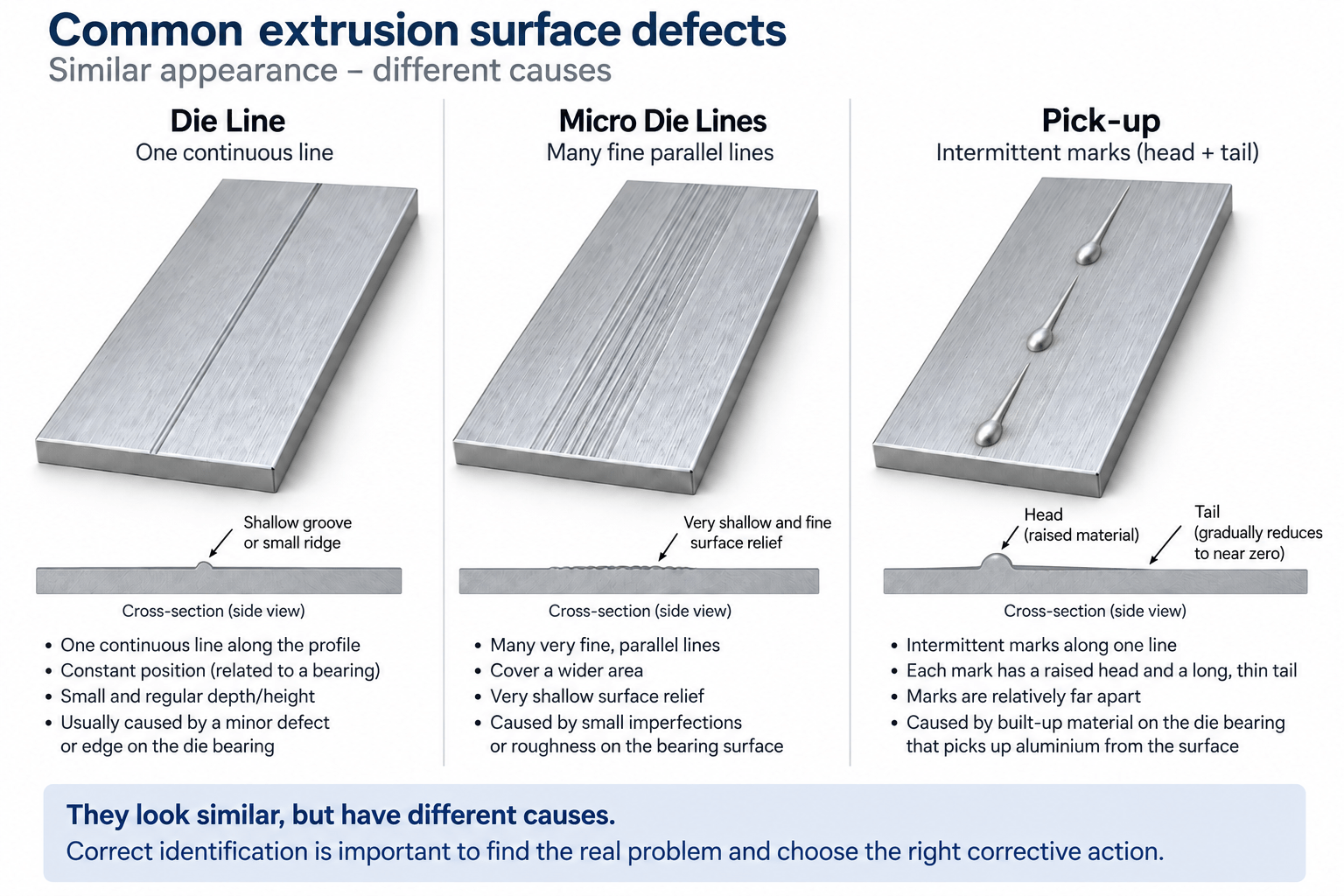 Figure 1. Typical surface appearance of Die Line, Micro Die Lines and Pick-up. The drawing is schematic and not to scale.
5. What E6 Etching Does
E6 alkaline etching removes aluminium from the surface. It changes the surface topography, rounds small peaks and shallow grooves, and produces the characteristic matte appearance.
Its effect therefore depends strongly on the depth and type of defect.
A shallow Die Line may become less visible or disappear. Fine Micro Die Line relief may be substantially reduced. Light Pick-up damage may also become less obvious, while deeper scoring, tearing or substantial surface damage can remain.
But E6 introduces another important diagnostic problem.
A physical longitudinal line and an optical longitudinal streak are not necessarily the same phenomenon.
This distinction can be summarized in one sentence:
E6 can remove a line. It can also reveal a streak. These are not necessarily the same defect.
A line is primarily a geometrical surface feature — a groove, ridge or other physical relief.
A streak is primarily a longitudinal visual difference.
After the physical Micro Die Lines have been reduced by etching, another longitudinal difference may become visible because different areas of the surface respond differently to etching. Near-surface microstructure, deformation, crystallographic texture and distribution of intermetallic particles can all influence this response.
Therefore, it is misleading to say that Micro Die Lines simply “become more visible” after etching. The original physical lines may actually have been reduced while a different optical phenomenon has become apparent.
6. What Happens After Anodizing
Anodizing should not be regarded as a surface-leveling process.
Significant grooves, ridges, Pick-up damage or other topographical defects remaining after pretreatment can influence the appearance of the final anodized surface.
At the same time, a longitudinal optical streak already revealed during E6 may remain visible after anodizing.
It is not necessary to assume that anodizing itself always increases the streak. The important point is that a defect first noticed on an anodized profile did not necessarily originate in the anodizing bath.
For difficult surface problems, compare the same profile at three stages:
Mill finish → After E6 → After anodizing
This simple comparison can provide much more information than examining only the finished anodized profile.
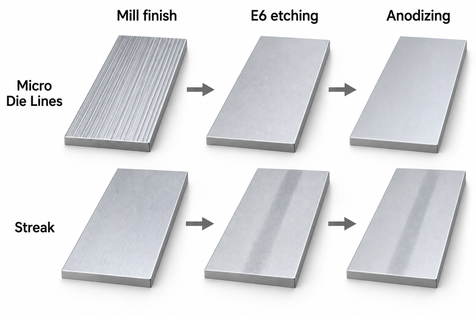 Figure 2. Different effects of E6 etching on Micro Die Lines and surface streaking.
E6 can reduce or remove fine surface relief, while differences in surface response may become visible as longitudinal streaks.
7. Corrective Actions
Corrective action should follow diagnosis.
For a Die Line, map the position of the defect on the profile back to the corresponding part of the bearing. Inspect for local grooves, depressions, raised irregularities, adhered aluminium, oxide or hard particles, wear and abnormal polishing or correction. Remember the inverse relationship between bearing geometry and the resulting profile surface. Correction should be local and controlled rather than unnecessary polishing of the complete bearing.
For Micro Die Lines, investigate the bearing condition together with extrusion conditions. Check bearing finish, wear, adhesion and deposits, but also extrusion speed, billet temperature, die temperature and resulting surface temperature. Compare profiles from the beginning and later stages of the die run.
For Pick-up, cleaning may restore the surface temporarily, but it does not necessarily remove the cause. Inspect the bearing area where material transfer repeatedly occurs and review extrusion speed, temperatures, local flow and die geometry.
When troubleshooting, change one parameter at a time where practical. If speed, temperature and die condition are all changed simultaneously, a good profile may be produced without learning which change actually solved the problem.
8. Quick Comparison
| Feature | Die Line | Micro Die Lines | Pick-up |
|---|---|---|---|
| Appearance | One distinct longitudinal line | Many very fine parallel lines | Separate, often comet-like marks |
| Continuity | Usually continuous | Usually continuous | Intermittent |
| Position | Usually fixed | Often over a wider area | Often repeats in the same general area |
| Surface character | Groove or ridge | Fine longitudinal relief | Roughness, scoring and/or transferred aluminium |
| Main mechanism | Local bearing irregularity | Extrudate–bearing interaction, near-surface deformation and microstructural effects | Adhesion, material transfer, build-up and detachment |
| During die run | Often relatively stable | May change gradually | Often variable or cyclic |
| Effect of E6 | Shallow line may reduce or disappear | Fine relief may substantially reduce | Light damage may reduce; severe damage remains |
| First check | Corresponding bearing location | Bearing condition + extrusion conditions | Bearing area where transfer repeatedly occurs |
This table is a first diagnostic guide, not an absolute classification. Real surface defects can involve more than one mechanism.
Conclusion
Die Lines, Micro Die Lines and Pick-up all follow the extrusion direction, but they should not be treated as the same defect.
A Die Line is normally a continuous geometrical feature associated with a local bearing condition. Micro Die Lines are much finer and involve interaction between the extrudate and bearing together with near-surface deformation and microstructural effects. Pick-up involves adhesion and material transfer, with build-up and detachment producing intermittent marks.
The best diagnosis combines appearance, continuity, position and behaviour during the die run.
Chemical pretreatment adds another layer to the problem. E6 can reduce shallow physical surface relief while revealing optical differences associated with the surface structure.
For this reason, comparison of the profile at mill finish, after E6 and after anodizing can be one of the most useful tools in surface-defect investigation.
The objective is not simply to make the visible defect disappear. It is to identify where and why the surface condition was created and correct the source.
References
1. P. K. Saha. Aluminum Extrusion Technology. ASM International, 2000.
ASM Digital Library
2. M. P. Clode and T. Sheppard. “Formation of Die Lines During Extrusion of AA6063.” Materials Science and Technology, Vol. 6, No. 8, 1990, pp. 755–763. DOI 10.1179/mst.1990.6.8.755.
Article page
3. Xiao Ma. Surface Quality of Aluminium Extrusion Products. PhD thesis, University of Twente, 2011. DOI 10.3990/1.9789077172728.
University of Twente
4. M. B. de Rooij, X. Ma, A. J. den Bakker and R. J. Werkhoven. “Surface Quality Prediction in Aluminum Extrusion.” Key Engineering Materials, Vol. 491, 2012, pp. 27–34. DOI 10.4028/www.scientific.net/KEM.491.27.
University of Twente publication record
5. A. F. M. Arif, A. K. Sheikh, S. Z. Qamar, M. K. Raza and K. M. Al-Fuhaid. “Product Defects in Aluminum Extrusion and Their Impact on Operational Cost.” 6th Saudi Engineering Conference, KFUPM, Vol. 5, 2002.
Original KFUPM paper
6. Global Advisory Group. Guidance “Terms and Definitions”, GAG 001, 3rd edition, 2011.
The Aluminum Association PDF
AI-assisted research and illustrations
This article was developed with the assistance of OpenAI ChatGPT. AI was used to search for and compare technical sources, analyse different explanations of defect mechanisms, check terminology, structure and edit the text, and develop the schematic illustrations. Technical conclusions and the final content were reviewed by Aluminium Guide.