A Guide to Aluminum Fluidity in Casting: Mastering Thin-Walled Components
Aluminum casting is a cornerstone of modern manufacturing. Engineers use it to create lightweight, durable parts for automotive, aerospace, and electronics industries. However, the success of any casting project depends on one vital property: fluidity.
This comprehensive guide breaks down the science of aluminum fluidity. You will learn why it matters for thin-walled parts, how to test it, and how to optimize it for different alloys using international material standards.
What is Aluminum Fluidity and Why Does It Matter?
In foundry terms, fluidity is not just the inverse of viscosity. It is a technological property. It describes the ability of molten metal to flow through narrow channels, fill every corner of a mold, and perfectly replicate complex details before solidifying.
[Molten Aluminum] ──> Enters Mold ──> Flows through Channels ──> Fills Cavity ──> Freezes (Stops)
                                      └─────── FLUIDITY WINDOW ───────┘
For engineers designing modern components, high fluidity is critical. Without it, several defects occur:
- Misruns: The metal cools too fast and freezes before completely filling the mold cavity.
- Cold Shuts: Two streams of molten metal meet but fail to fuse completely due to low temperature.
- Surface Defects: The metal cannot press firmly against the mold walls, leading to poor surface finish.
- Gas Porosity: Low fluidity traps air and gases inside the mold instead of pushing them out through vents.
The Challenge of Thin-Walled Aluminum Castings
Modern industries constantly demand lighter components to increase energy efficiency. This trend makes thin-walled castings (walls under 2–3 mm thick) highly desirable.
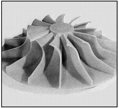 Figure 1 – Thin-veins or intricate thin walled structures require a high degree of fluidity to avoid misruns [EAA]
When molten aluminum enters a thin channel, it faces severe challenges:
- Rapid Chilling: Thin walls mean a very high surface-area-to-volume ratio. The mold extracts heat from the liquid metal instantly.
- Capillary Action: Narrow gaps resist the flow of liquid metal, requiring higher pressure or superior fluidity to pass through.
- Oxide Skin Surface Tension: Aluminum instantly forms a tough aluminum oxide (Al₂O₃) skin when exposed to oxygen. In a tight space, this skin acts like a strong rubber balloon, physically holding back the metal flow.
To cast a successful thin-walled component, foundry engineers must maximize the alloy’s fluidity window.
Standard Fluidity Testing Methods
Foundries cannot measure fluidity with a standard laboratory viscometer. They use specific empirical tests that mimic actual casting conditions. The distance the metal travels before it stops defines its fluidity value.
1. The Spiral Test (Cury Test)
The spiral test is the most popular method in global foundries.
- How it works: Molten metal is poured into a pouring basin, flowing through a downsprue into a long, horizontally coiled spiral channel with a trapezoidal cross-section.
- Measurement: The length of the solidified spiral channel in centimeters or inches represents the fluidity.
- Limitation: It is highly sensitive to the operator’s pouring speed and height.
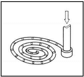 Figure 2 – The fluidity spiral, or sand spiral, is one of the oldest and simplest fluidity tests [EAA]
2. The Vacuum Suction Test
To eliminate human error during pouring, researchers use vacuum testing.
- How it works: A narrow quartz or glass tube connects to a regulated vacuum system. The tube lowers into the molten aluminum bath, and the vacuum sucks the metal upward.
- Measurement: The height of the metal column drawn into the tube before solidification determines the fluidity.
- Advantage: Highly repeatable, precise control over pressure and suction rates.
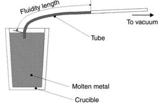 Figure 3 – Vacuum fluidity test [ASM Handbook, Volume 15: Casting]
3. The U-Shaped (Nekhendzi-Samarin) Test
This test specifically evaluates suitability for thin-walled parts.
- How it works: The mold features multiple vertical, U-shaped channels of varying thickness.
- Measurement: Engineers observe which specific channel thickness fills completely and which fails.
Alloy Composition: The Primary Driver of Fluidity
An aluminum alloy’s chemical makeup dictates its solidification mode, which directly impacts fluidity.
The Role of Silicon (Si)
Silicon is the most effective element for boosting aluminum fluidity. When you add silicon to aluminum, it lowers the melting point and forms an eutectic mixture at approximately 11.7% to 12.6% Silicon.
Eutectic alloys behave like pure water; they change from 100% liquid to 100% solid at a single temperature point (577°C). Because there is no sluggish “mushy zone” during cooling, eutectic alloys achieve maximum fluidity.
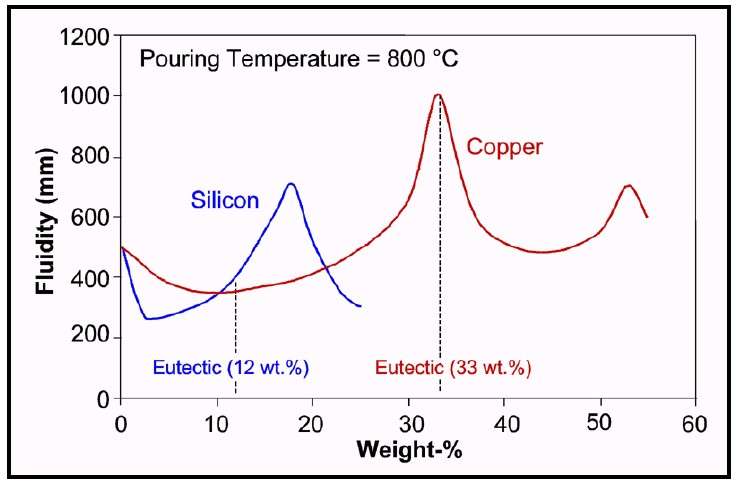 Figure 4 – [EAA]
Fluidity of US (AA) and European (EN) Aluminum Alloy Families
| Alloy Group | US Grade (AA) | European Grade (EN) | Fluidity Level | Solidification Characteristics |
|---|---|---|---|---|
| Al-Si (Silumins / Near-Eutectic) | A413.0, A356.0, 360.0 | EN AC-44300, EN AC-43300 | Excellent / Highest | Narrow mushy zone, smooth solidification front. Ideal for complex geometries and micro-textures. |
| Al-Cu (Copper-based) | A206.0, 295.0, B295.0 | EN AC-21000, EN AC-21100 | Moderate to Low | Wide solidification range. Prone to hot tearing and micro-shrinkage defects. Requires extra superheat. |
| Al-Mg (Magnaliums) | A535.0, 518.0 | EN AC-51100, EN AC-51300 | Poor / Lowest | Wide mushy zone. High internal resistance to flow and heavy oxidation limits performance in thin molds. |
Key Factors Influencing Aluminum Fluidity
Beyond chemistry, several process variables dictate how far molten aluminum can flow.
1. Pouring Temperature (Superheat)
Superheat is the thermal energy added to the metal above its liquidus temperature. Fluidity increases linearly with increasing pouring temperature.
- Extra superheat provides more time for the metal to travel and lose energy before crystals start forming.
- Caution: Overheating aluminum causes high gas absorption (hydrogen) and increases iron pickup from tools, causing structural brittleness.
2. Mold Temperature and Coatings
Cold molds freeze metal instantly. Preheating permanent steel molds (dies/kockils) to 150°C – 300°C delays solidification, drastically boosting filling capacity. Applying insulating mold washes or coatings also shields the liquid metal from sudden thermal shock.
3. Surface Tension and Oxide Inclusion Contamination
As mentioned, aluminum oxide (Al₂O₃) films reduce flow. Similarly, suspended non-metallic inclusions act like rocks in a stream, creating physical blockages. Foundries use fluxing, degassing treatments, and ceramic foam filters to clean the melt and restore optimal fluidity.
Actionable Tips for Casting Thin-Walled Parts
If you are manufacturing thin-walled parts, apply these practical troubleshooting rules:
- Choose Eutectic or Near-Eutectic Alloys: Select standard international grades like A413.0 or EN AC-44300 whenever your design features thin ribs or micro-textures.
- Optimize Gate Designs: Design wide, thin gates to distribute metal quickly across the thin wall sections before thermal energy drops.
- Use Vacuum-Assisted or Die Casting: Rely on high-pressure die casting (HPDC) or vacuum mold evacuation to overcome capillary friction.
- Implement Grain Refinement: Introduce master alloys containing Titanium and Boron (Al-Ti-B) to create fine, equiaxed grains that flow smoother than coarse dendritic structures.