Aluminium Casting Defects: Causes, Prevention and Inspection
Aluminium casting can produce complex and reliable engineering components, but the casting process can also create defects that affect strength, fatigue life, corrosion resistance and dimensional stability.
The important point is that casting defects are rarely caused by one factor alone.
A defect may result from the combination of:
alloy + melt quality + mould design + filling + feeding + solidification + heat treatment.
For this reason, the best approach is not simply to inspect a casting and reject defective parts. A good foundry tries to prevent defects by controlling the process from melting to final inspection.
1. Porosity
Porosity is one of the most common defects in aluminium castings.
There are two major types:
- gas porosity;
- shrinkage porosity.
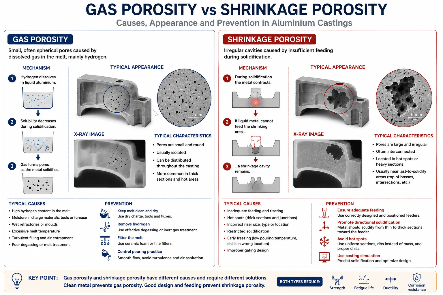
Gas porosity is usually associated with dissolved hydrogen in the liquid aluminium. Hydrogen becomes less soluble as the metal solidifies and can form small internal pores.
Shrinkage porosity occurs because aluminium contracts during solidification. If liquid metal cannot feed the contracting region, internal cavities can form.
Porosity is particularly dangerous when it occurs in highly stressed regions.
A small isolated pore in a low-stress area may have little effect. A large interconnected pore near a stress concentration can significantly reduce fatigue strength.
How to reduce porosity
Good process control includes:
- clean charge materials;
- controlled melting temperature;
- hydrogen removal;
- effective melt filtration;
- good gating design;
- correct riser and feeder design;
- controlled solidification;
- avoidance of unnecessary turbulence.
Vacuum-assisted processes can also reduce gas-related defects in suitable applications.
2. Oxide Films and Inclusions
Aluminium reacts rapidly with oxygen and forms an oxide film on the surface of liquid metal.
When liquid metal becomes turbulent, oxide films can be folded into the melt. These folded films are sometimes called bifilms.
They can behave like internal cracks and may significantly reduce ductility and fatigue performance.
Other inclusions can come from:
- furnace lining;
- refractory materials;
- slag;
- dirty charge materials;
- poorly controlled melt treatment.
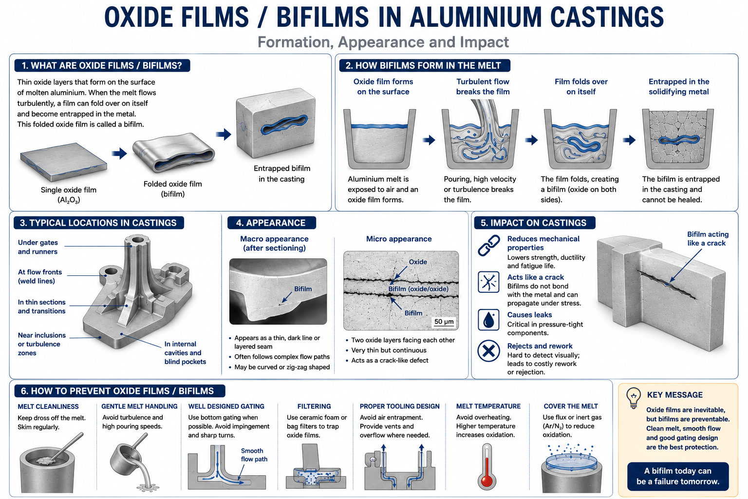 Figure 3 – Oxide Films – Bifilms in Aluminium Casting
Prevention
The best approach is to keep the metal clean and avoid unnecessary turbulence.
Important measures include:
- clean melting equipment;
- clean charge materials;
- controlled pouring;
- proper skimming;
- effective filtration;
- good gating design.
The design of the filling system is therefore part of the quality of the final casting.
3. Hot Cracking
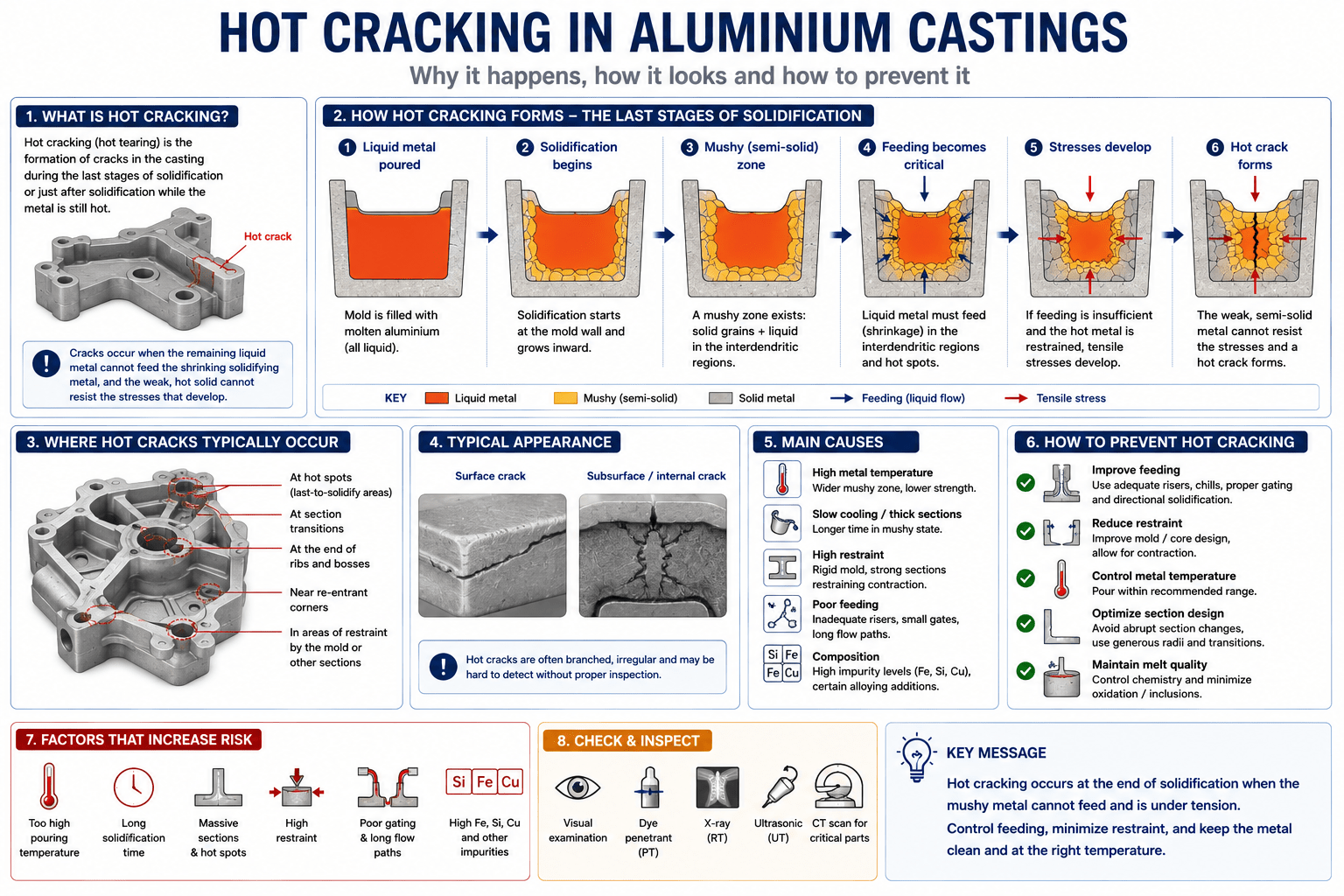
Hot cracks occur during the final stages of solidification, when the metal has insufficient strength to withstand contraction.
They are more likely when the casting design restricts shrinkage.
Typical causes include:
- sharp corners;
- large changes in wall thickness;
- poor feeding;
- excessive restraint;
- unsuitable alloy selection;
- high thermal stresses.
Prevention
Hot cracking can often be reduced by:
- using generous fillets;
- avoiding sudden section changes;
- improving feeding;
- reducing restraint;
- choosing an alloy with suitable hot-tearing resistance;
- improving mould and process control.
Good casting design can prevent many hot-cracking problems before production begins.
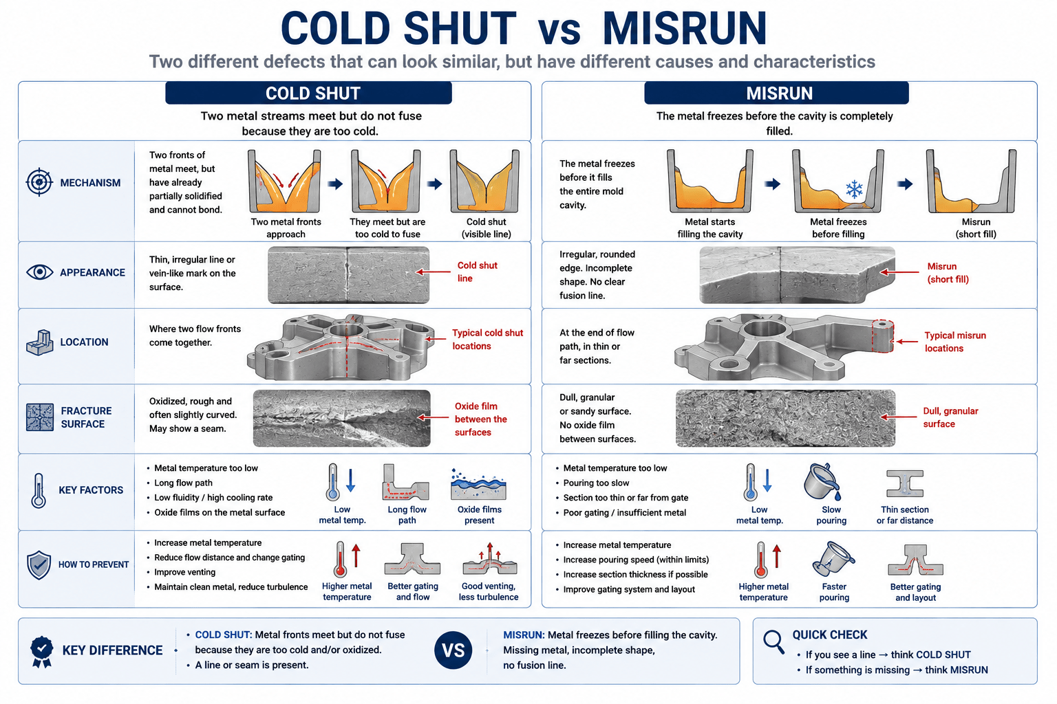
4. Cold Shut and Misrun
A cold shut occurs when two streams of liquid metal meet but do not properly fuse.
A misrun occurs when the metal does not completely fill the mould.
These defects are commonly associated with insufficient metal temperature, poor flow or excessive heat loss during filling.
Typical causes include:
- low pouring temperature;
- low mould temperature;
- poor gating;
- thin sections;
- long flow distances;
- inadequate filling speed.
Prevention
The engineer can improve filling by:
- optimising the gating system;
- controlling metal temperature;
- controlling mould temperature;
- avoiding unnecessarily thin sections;
- reducing excessive flow length;
- using casting simulation.
The solution is not always to increase the pouring temperature. Excessive temperature can increase oxidation, gas absorption and other problems.
5. Shrinkage Cavities
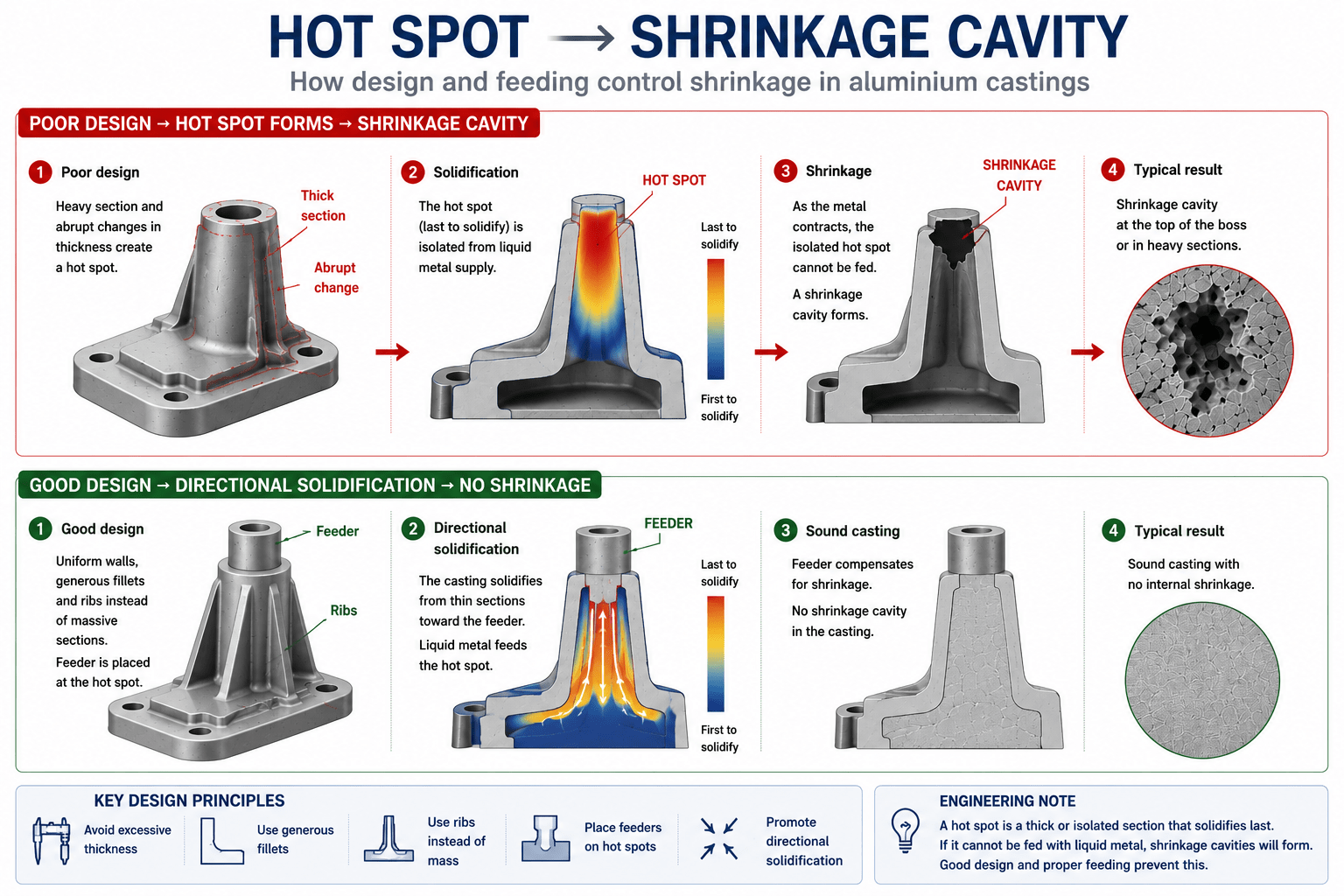
Shrinkage cavities are larger internal or surface defects caused by insufficient feeding during solidification.
They are particularly common in heavy sections and isolated masses of metal.
A common design mistake is to create a large thick boss or heavy intersection because it appears mechanically strong.
However, this area may become a hot spot that solidifies last.
If there is no effective liquid-metal supply, shrinkage can develop inside the component.
Prevention
The best solutions include:
- reducing unnecessary section thickness;
- using ribs instead of massive sections;
- positioning feeders correctly;
- improving directional solidification;
- using chills where appropriate;
- using casting simulation.
This is a good example of why casting design and foundry technology cannot be separated.
6. Gas Defects
Hydrogen is particularly important in aluminium casting.
Liquid aluminium can absorb hydrogen from moisture and other sources. During solidification, hydrogen becomes less soluble and can form pores.
Sources of hydrogen can include:
- wet charge materials;
- moisture in the furnace;
- wet tools;
- humid mould materials;
- contamination;
- excessive melt exposure.
Prevention
Foundries commonly use melt treatment to reduce dissolved hydrogen.
Depending on the process, this may include:
- rotary degassing;
- inert gas treatment;
- filtration;
- controlled furnace practice.
The condition of the charge material is equally important.
7. Inclusions
Inclusions are unwanted foreign particles inside the casting.
They may include:
- oxides;
- intermetallic particles;
- refractory fragments;
- slag;
- other non-metallic material.
Inclusions can reduce ductility and become crack initiation sites under fatigue loading.
Good melt preparation and filtration are therefore especially important for structural castings.
8. Dimensional Distortion
Not all casting defects are internal.
Aluminium castings can also distort during cooling because different sections contract at different rates.
Distortion can be caused by:
- uneven wall thickness;
- residual stresses;
- mould constraints;
- asymmetric geometry;
- heat treatment.
Heat treatment can sometimes increase distortion because the casting is heated and quenched.
For precision castings, dimensional inspection should therefore be performed after the complete manufacturing process, including heat treatment and machining where applicable.
9. Heat-Treatment Problems
Many aluminium casting alloys are heat treatable.
T6 treatment normally includes:
solution treatment → quenching → artificial ageing.
Incorrect heat treatment can cause:
- insufficient strength;
- excessive distortion;
- dimensional changes;
- residual stresses;
- loss of ductility;
- inconsistent properties.
The actual heat-treatment cycle should therefore be controlled and recorded.
For critical components, traceability of the heat-treatment batch can be as important as chemical composition.
10. How Are Casting Defects Detected?
Different defects require different inspection methods.
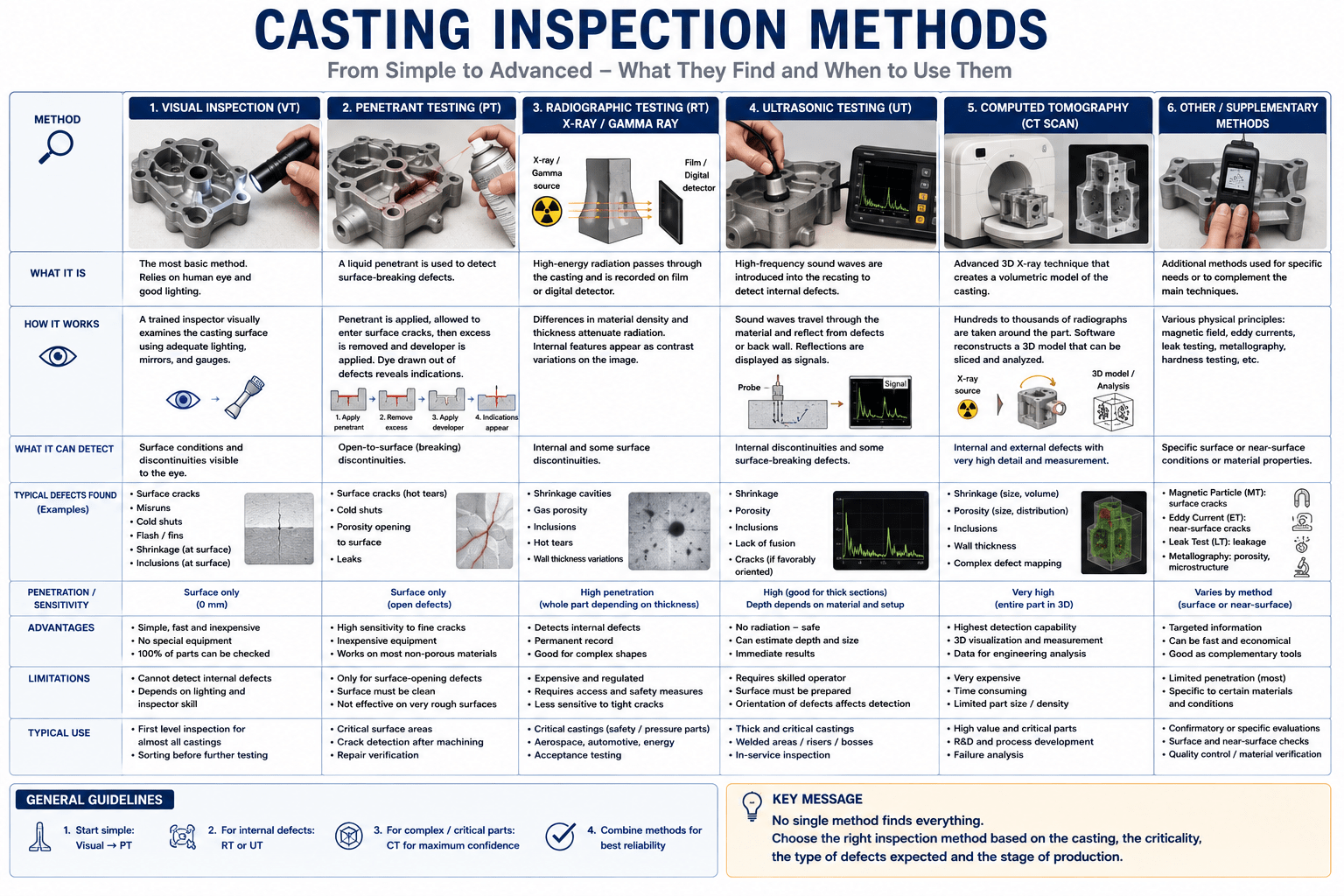
Visual Inspection
Useful for:
- surface cracks;
- cold shuts;
- misruns;
- surface porosity;
- dimensional problems.
It cannot reliably detect internal defects.
Dye Penetrant Testing
Useful for detecting surface-breaking cracks and discontinuities.
It is particularly useful when surface integrity is important.
Radiographic Testing
X-ray or gamma-ray radiography can reveal many internal defects, including:
- gas porosity;
- shrinkage cavities;
- inclusions.
It is widely used for critical aluminium castings.
Ultrasonic Testing
Ultrasonic testing can be useful for detecting internal discontinuities, especially in larger sections.
Its effectiveness depends strongly on casting geometry, material structure and defect type.
Computed Tomography
Industrial CT can provide a three-dimensional view of internal casting defects.
It is particularly useful for development work and complex components, although cost and component size can limit its use for routine production.
11. Acceptance Criteria Are Part of the Design
One of the biggest mistakes is to specify:
“The casting must be free from defects.”
This is not a useful engineering requirement.
Almost every casting contains some level of microstructural variation or small discontinuities.
The correct approach is to define:
- defect type;
- defect size;
- defect location;
- defect density;
- critical zones;
- inspection method;
- acceptance level.
A small pore in a low-stress region may be acceptable.
The same pore in a fatigue-critical section may not be acceptable.
Therefore:
defect acceptance must be related to the function of the component.
12. Design Critical Zones Before Casting
A good engineering drawing should identify critical areas.
These may include:
- bolt holes;
- bearing seats;
- hydraulic sealing surfaces;
- highly loaded ribs;
- fatigue-critical sections;
- welded areas;
- areas with high stress concentration.
The foundry can then focus process control and inspection on these locations.
This is much more effective than applying exactly the same inspection requirements to every cubic millimetre of the casting.
Conclusion
Casting defects cannot be eliminated simply by improving final inspection.
The best solution is to control the complete casting process:
clean metal + suitable alloy + good mould design + controlled filling + directional solidification + correct heat treatment + appropriate inspection.
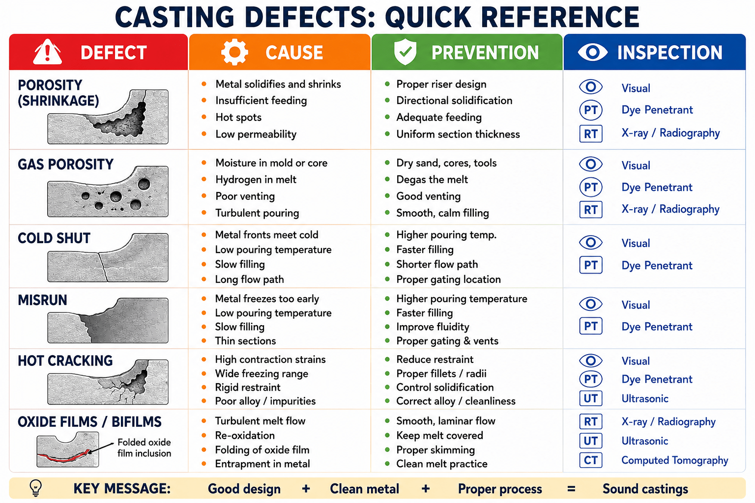
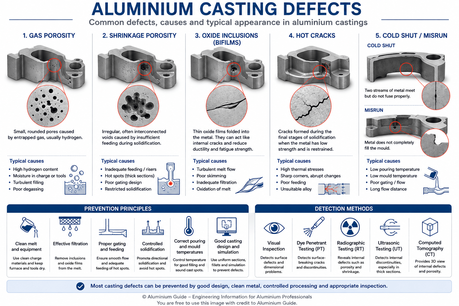
Figure 8 – Aluminium Castings Defects
The most important lesson for the designer is simple:
A casting defect is often a design problem before it becomes a quality-control problem.
Good casting design reduces the probability of defects before the metal enters the mould.
That is why the mechanical designer, foundry engineer, metallurgist and quality engineer should work together from the beginning of the project.
References
- EN 1706:2020+A1:2021 — Aluminium and aluminium alloys — Castings — Chemical composition and mechanical properties
- ISO 8062-3:2023 — Geometrical product specifications — Dimensional and geometrical tolerances and machining allowances for castings
- European Aluminium — Aluminium Automotive Manual: Cast Alloys and Products
- European Commission JRC — Eurocode 9: Design of Aluminium Structures