The Fibre Grain Structure of Aluminium Forgings
Aluminium forgings were first used about 90 years ago for the aerospace industry. Since then, there has been a rapid increase of their use in other fields of application.
Aluminium forgings provide the following advantages:
- High strength and low weight
- Good corrosion resistance (for most aluminium alloys)
- The fibre grain structure can be arranged to correspond to the main loading direction leading to high strength and fatigue properties.
Figure 1
Figure 2 illustrates an example for the fibre grain structure in the longitudinal direction for different fabricating processes. During forging, an attempt is made to create a fibre structure corresponding to the main loading direction. Castings do not exhibit a fibre structure. During fabrication by machining of an extruded semiproduct, for example, individual fibres are cut. This leads to a reduction of the fatigue strength.
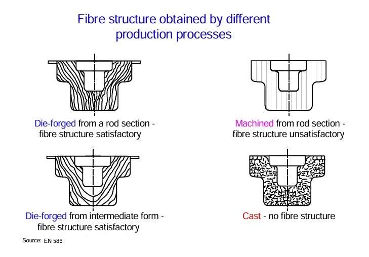 Figure 2
The fibre structure depends to a large extent on the type and form of the starting material. Because of the good extrudability of aluminium, it is advisable to use extruded sections as pre-fabricates for the forgings. The final part then exhibits a mixed fibre structure.
 Figure 3
Figure 4 shows the most important parameters which have an influence on the material flow during forging. The type of material flow itself affects a number of forming parameters and index values of the workpiece. The fibre structure affects the statical and dynamical strength properties in particular, as well as the stress corrosion properties of certain alloys (aluminium-zinc-magnesium-copper).
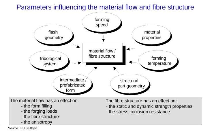 Figure 4
The position of the parting plane of the tool has an influence on the material flow during forming. Figure 5 illustrates how the material flow and consequently the fibre structure can be improved by shifting the parting plane from the middle of the section to the top. The section of the modified die parting shows a more uniform fibre structure at the rounding.
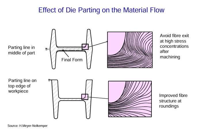 Figure 5
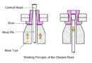
Figure 6 illustrates the process of form filling in closed dies with and without flash. During forming in dies with flash, the extra material is pressed out of the die cavity into the flash or flash cavity. The geometry of the flash gap has a deciding influence on the forging load and the form filling of the die cavity. During forging without flash, the whole material remains in the die filling it out completely. Both, forging stock and finished forging, have to have identical masses. The material flow is controlled by the geometry of the raw stock, the flow stress and the tribological conditions at the contact zone of the die.
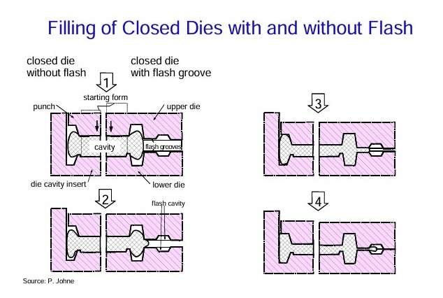 Figure 6
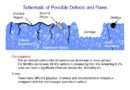
Figure 7 shows the effect of increasing die radii on material flow during die filling. Folds can be effectively avoided. The schematic diagram illustrates, how the material flow is affected by the design of the fillet radii. When the radii are chosen properly, the material hugs the radius of the die cavity during forming and then flows up along the walls. If the radius is too small, then the material pulls away from the die cavity, coming to rest on the opposite wall from where it then rises up. On reaching the top of the cavity, the material is redirected downwards and fills out the cavity. Consequently, cold shuts form and laps occur where the redirected material glides over the material flowing up from the bottom leading to a high loss of strength properties at this location.
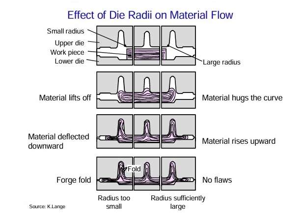 Figure 7
The source:
TALAT Lecture 3403 – Designing of Forgings / K. Siegert, D. Ringhand and R. Neher – European Aluminium Association – 1994