Streaking on Aluminium Extrusions: Causes, Identification and Troubleshooting
1. Introduction
Longitudinal streaks are among the most difficult surface appearance problems on aluminium extrusions. A streak may appear as a lighter or darker band running in the extrusion direction. It can become clearly visible after E6 etching or anodizing even when the mill-finish surface showed little or no obvious defect.
This makes streaking different from defects such as a Die Line or Pick-up. A Die Line is primarily a geometrical surface feature. Pick-up involves local adhesion and material transfer at the die bearing. A streak, however, is primarily a difference in appearance between neighbouring areas of the extrusion surface.
The visible band does not by itself identify its cause.
Similar-looking streaks may result from differences in metal flow and deformation, local thermomechanical conditions, grain structure and crystallographic texture, distribution of intermetallic particles, billet metallurgy, or longitudinal weld regions in porthole-die extrusions. Cooling can also contribute to the resulting microstructural differences.
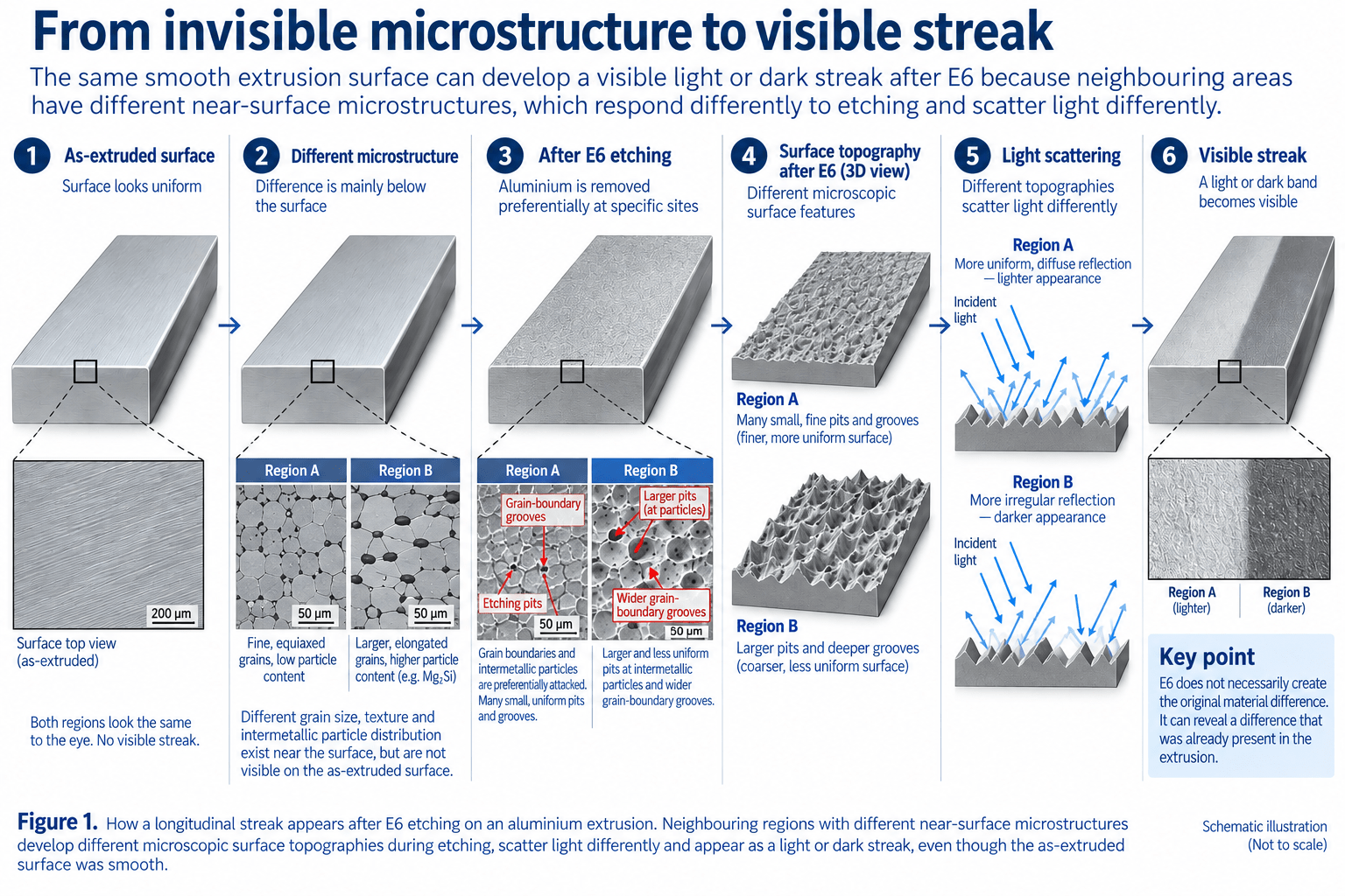
These differences may have little visual effect on the as-extruded surface. During alkaline etching, however, neighbouring areas can develop different microscopic surface topographies. They then reflect and scatter light differently, producing a visible streak. This general mechanism is well established for anodized 6xxx extrusions.
For this reason, a streak first noticed after anodizing should not automatically be classified as an anodizing defect.
The useful question is not simply:
“What kind of streak is this?”
It is:
“What caused these neighbouring areas of the extrusion to respond differently to surface treatment?”
This article examines the main mechanisms of streak formation on 6xxx-series aluminium extrusions and presents a practical approach to identifying their origin.
2. What Is a Streak?
A streak is a longitudinal band on the extrusion surface that differs visually from the surrounding area. It may appear lighter or darker and may extend for a considerable distance along the profile.
The important point is that a streak is primarily an appearance difference, not necessarily a groove, ridge or other measurable geometrical defect.
A Die Line normally has physical surface relief. It may be a groove or ridge produced continuously at a particular location of the die bearing.
Micro Die Lines are much finer longitudinal surface features. Their formation is more complex, but they still involve physical surface topography. Research on AA6063 shows that their origin involves extrudate–die interaction, deformation structure and the shear zone rather than simply reproducing microscopic bearing roughness.
Pick-up is an intermittent defect associated with adhesion and material transfer at the die bearing.
A streak can be different. The surface may feel smooth while the contrast results primarily from a difference in optical response.
A streak is an optical symptom
For practical diagnosis:
Line → look for surface geometry.
Streak → look for the reason why neighbouring surface areas appear different.
Die Lines, Micro Die Lines and Pick-up are discussed separately in our article Die Lines, Micro Die Lines and Pick-up in Aluminium Extrusion.
This distinction is not absolute. Local metal flow, deformation and temperature can affect both microscopic topography and near-surface microstructure. But a visible longitudinal band should not automatically be interpreted as a scratch or die mark.
Why E6 can reveal a streak
E6 alkaline etching removes aluminium and produces a matte surface.
The resulting microscopic topography depends partly on the underlying microstructure. Research on 6xxx extrusion streaking identifies etching pits, grain-boundary grooves and grain etching steps among the microscopic surface features that influence diffuse reflection. Their severity can vary with intermetallic-particle distribution, grain size and crystallographic texture.
Neighbouring longitudinal regions with different microstructures can therefore develop slightly different surfaces during E6 and scatter light differently.
This leads to an important distinction:
E6 does not necessarily create the original material difference. It may reveal a difference that was already present in the extrusion.
What does anodizing do?
Anodizing should not be regarded as a surface-leveling operation. If neighbouring regions already have different microscopic surface conditions after pretreatment, the appearance difference may remain visible on the anodized profile.
Therefore:
A streak visible after anodizing is not, by itself, evidence that anodizing caused the streak.
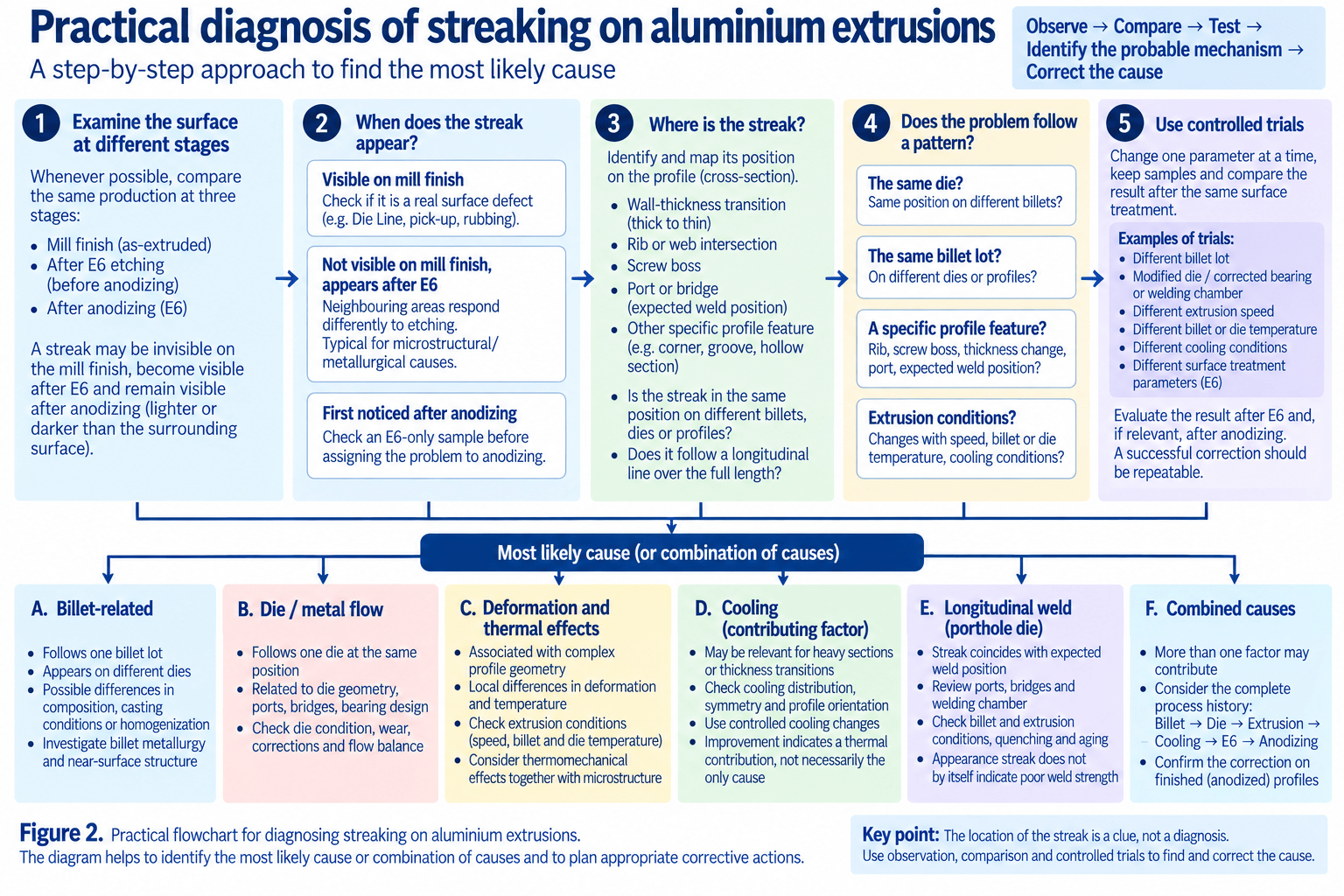
Whenever possible, compare the same production at three stages:
Mill finish → After E6 → After anodizing
3. Why Streaks Form
Streaking should not be treated as a single defect with a single cause. Similar visible bands can originate at different stages of billet production and extrusion.
For troubleshooting, classification by formation mechanism is more useful than classification by appearance alone.
3.1 Billet-related metallurgical differences
Some differences may originate before the billet enters the press.
Variations created during billet solidification and modified during homogenization can influence the microstructure that reaches the extrusion process. The distribution and condition of intermetallic and second-phase particles can subsequently affect surface response during etching.
A billet-related contribution should be investigated when similar streaking follows a billet lot across different dies or profile geometries.
However, billet origin should not be assumed simply because a streak appears after anodizing. Extrusion itself can create strong local microstructural differences.
3.2 Die geometry and non-uniform metal flow
The die does more than define the profile cross-section. It controls how different parts of the metal stream approach the opening and pass through the bearings.
Different wall thicknesses, ribs, screw bosses, junctions, ports, bridges and other geometrical features can produce different local flow and deformation conditions.
Research on anodized 6xxx extrusions links die streaks to heterogeneous microstructures produced by localization of deformation associated with non-uniform metal flow. Die design and extrusion conditions both influence this process.
The extrusion may therefore leave the press without an obvious macroscopic surface defect but contain neighbouring longitudinal regions that respond differently during E6.
This explains an important production observation:
A streak can follow the die without being a Die Line.
3.3 Local deformation and thermal effects
Plastic deformation and friction generate heat during extrusion. These effects are not necessarily uniform across a complex profile.
Neighbouring regions can consequently experience different combinations of deformation and temperature and develop different grain structures, textures or particle distributions.
These differences may be difficult to see on the mill-finish extrusion but become visible after etching.
For this reason, the concept of thermomechanical streaking is useful: deformation and thermal history should often be considered together.
Extrusion speed can influence streaking, but improvement at lower speed does not by itself prove that speed was the root cause. Changing speed also changes deformation rate and thermal conditions.
3.4 Cooling as a contributing factor
The thermal history continues after the profile leaves the die.
Different cooling histories can contribute to microstructural differences across a complex 6xxx extrusion. Cooling should therefore be investigated when streaking corresponds to heavy sections or when controlled changes in quenching affect the defect.
However, cooling should not automatically be assigned as the cause simply because the streak occurs near a thick-to-thin transition. Metal flow, deformation and thermal history may all contribute at the same location.
3.5 Longitudinal weld regions in porthole-die extrusions
Hollow profiles introduce another possible source of longitudinal appearance differences.
In a porthole die, the billet is divided into separate metal streams by bridges. The streams subsequently rejoin under pressure, creating continuous longitudinal solid-state welds.
The material around these regions can have a different thermomechanical and microstructural history from surrounding material and may therefore respond differently to etching and anodizing.
Longitudinal weld streaking is a recognized problem on anodized hollow profiles. Recent industrial research treats it as a process-chain problem involving billet production, extrusion, quenching, artificial aging and anodizing rather than as the result of one operation alone.
If a streak consistently corresponds to the expected position of a longitudinal weld, that region should therefore be investigated before the defect is classified as a conventional Die Line or general anodizing problem.
4. One Streak Can Have More Than One Cause
Extrusion is a coupled thermomechanical process. Metal flow, deformation, friction, temperature and cooling interact.
Consider a screw boss connected to a relatively thin wall. The boss can disturb local metal flow, require different bearing control, alter deformation, affect local temperature and subsequently cool differently from the neighbouring wall.
The final streak may therefore be the result of several interacting effects.
The position is a clue, not a diagnosis
A streak repeatedly appearing at a web intersection, screw boss, wall-thickness transition, port or longitudinal weld position strongly suggests a relationship with that feature.
But:
Position identifies where to investigate. It does not identify the mechanism.
The same die can change with time
The production die is not necessarily identical to its original drawing.
Bearings wear. Aluminium may adhere locally. Dies are polished and corrected. Local geometry and restraint can change during service.
Therefore:
If the profile was previously good from the same die, investigate what has changed.
Process changes can help — but can also mislead
If a streak becomes weaker when extrusion speed is reduced, the observation is useful. But speed changes several conditions simultaneously.
The same caution applies to billet temperature, die temperature and quenching.
Where practical:
Change one parameter → inspect the result → compare with the previous condition.
Think in terms of process history
For difficult streaking problems, follow the affected longitudinal region through the complete process:
Billet → Die → Metal flow → Deformation and temperature → Cooling → E6 etching → Anodizing
5. Practical Diagnosis of Streaking
A useful investigation begins with observations, not with a defect name.
5.1 Compare different surface stages
Keep samples, whenever possible, from:
Mill finish → After E6 → After anodizing
If the mark is already visible in mill finish, first determine whether it is actually a streak or a physical defect such as a Die Line, Micro Die Lines, Pick-up, scratching or rubbing.
If mill finish appears uniform but a band develops after E6, investigate why neighbouring regions respond differently to etching.
If the defect is first noticed after anodizing, examine an E6-only sample before assigning the problem to anodizing.
Do not discard the mill-finish evidence.
Once the profile has been etched, part of the evidence about the original extrusion surface has already been removed.
5.2 Map the streak onto the cross-section
Record its exact transverse position and compare it with:
- wall-thickness transitions;
- ribs and web intersections;
- screw bosses;
- expected longitudinal weld positions;
- regions requiring strongly different flow control.
Remember:
Fixed position does not automatically mean a damaged bearing.
5.3 Does the problem follow the die?
If one die repeatedly produces a streak in the same location, investigate the die and local flow conditions.
Ask:
Was the streak present when the die was new?
If not, check die corrections, bearing polishing, wear, deposits and changes in extrusion conditions.
5.4 Does the problem follow the billet lot?
If similar streaking appears on several dies or different profiles produced from the same billet lot, investigate billet metallurgy.
Compare, where available:
- cast number and billet source;
- composition;
- casting history;
- homogenization conditions;
- microstructural homogeneity.
Useful comparisons include:
Same die + different billet lots
and
Same billet lot + different dies
5.5 Check extrusion history
Record good and defective production conditions, including billet temperature, die temperature, extrusion speed and exit temperature.
Also observe behaviour during the run.
Does the streak appear from the first billet? Does it develop gradually? Does it change after die cleaning or when extrusion conditions are changed?
5.6 Check cooling separately
Where cooling appears relevant, check profile orientation, cooling symmetry and the distribution of air or water.
A controlled cooling change can provide useful evidence.
But:
Improvement after changing cooling indicates a thermal contribution; it does not by itself prove one particular mechanism.
5.7 Consider longitudinal welds
For porthole-die profiles, compare streak position with the expected longitudinal weld locations.
Coincidence should trigger investigation of the weld-region process history, not an automatic conclusion that weld strength is inadequate. The literature shows that longitudinal weld streak visibility can be influenced by multiple stages of the process chain.
5.8 Use controlled trials
For difficult problems:
Document initial condition → Change one parameter → Extrude a controlled sample → Apply the same surface treatment → Compare
Keep the corresponding samples.
6. Corrective Actions
There is no universal correction for streaking.
6.1 If the evidence points to the billet
Compare billet lots under otherwise similar production conditions. Review casting, composition, homogenization and microstructural information where available.
The objective is to establish a repeatable relationship between billet condition and surface appearance before modifying satisfactory dies.
6.2 If the evidence points to the die or metal flow
Examine local bearing conditions, previous corrections, ports, bridges, welding chambers, flow restrictions, junctions and other geometrical features.
The objective is not only correct profile dimensions or overall exit velocity. Neighbouring surface regions should also avoid unnecessarily different thermomechanical histories.
Therefore:
Good dimensional flow balance does not necessarily guarantee uniform anodizing appearance.
6.3 If extrusion conditions affect the streak
Use controlled trials with speed, billet temperature and die temperature.
Where possible, record actual exit temperature together with extrusion speed.
Improvement at lower speed shows process sensitivity; it does not automatically identify high speed as the fundamental cause.
6.4 If cooling is involved
Investigate cooling distribution rather than simply increasing cooling intensity.
Depending on the process, relevant factors may include profile orientation, air or water distribution, nozzle arrangement and cooling timing.
The objective is more uniform and controlled cooling where practical.
6.5 If the streak corresponds to a longitudinal weld
Review metal-flow balance around bridges and ports, the welding chamber, extrusion conditions and the wider process chain.
Importantly:
Appearance and mechanical integrity are different questions.
A visible longitudinal weld streak does not by itself demonstrate inadequate weld strength.
6.6 Do not use E6 as the primary correction
Additional etching may reduce some appearance differences, but it also means more aluminium removal, greater chemical consumption and greater wastewater-treatment load.
More importantly, it may hide rather than eliminate the extrusion-related cause.
The preferred sequence is:
Identify the mechanism → Correct the material or extrusion cause where possible → Use the normal E6 process to produce the specified finish.
6.7 Verify the correction through the complete finishing route
If the customer receives an E6 anodized product, the corrective trial must ultimately be evaluated after the same finishing route.
A successful correction should be repeatable.
7. Common Diagnostic Mistakes
“It appeared after anodizing, so anodizing caused it”
Not necessarily. Streaking often becomes apparent only after surface treatment. This difficulty is specifically recognized in research on anodized 6xxx extrusions.
“It is always in the same position, so the bearing is damaged”
A fixed location may instead correspond to a permanent feature of the profile or die.
Fixed position identifies a location. It does not identify the mechanism.
“Lower speed removed it, so speed was the root cause”
Lower speed changes deformation and thermal conditions simultaneously.
It demonstrates process sensitivity, not necessarily root cause.
“The streak follows a longitudinal weld, so the weld is poor”
A visible weld streak is an appearance observation, not a mechanical weld-strength test.
“More E6 removed it, so the problem is solved”
The visible contrast may have been reduced without correcting its source.
“The die produces correct dimensions, so the die cannot be responsible”
Dimensional accuracy and uniform surface response after etching are different requirements.
“The name of the streak tells us its cause”
Streak terminology is not completely consistent between technical sources.
A safer approach is:
Observe → Locate → Compare → Test → Identify the probable mechanism → Then name the defect.
8. Quick Diagnostic Guide
| Observation | What it suggests | What to check next |
|---|---|---|
| Uniform mill finish; streak appears after E6 | Different etching response | Microstructure, profile geometry, metal flow, billet history |
| Follows one die at one position | Die/flow/thermomechanical contribution | Bearing condition, corrections, ports, bridges, local geometry |
| Follows one billet lot across different dies | Billet-related contribution | Cast, composition, homogenization, microstructure |
| At screw boss or thickness transition | Several mechanisms possible | Flow, deformation, temperature and cooling |
| Changes strongly with speed | Process sensitivity | Speed together with exit temperature and controlled trials |
| Changes with cooling | Thermal contribution | Cooling distribution and profile orientation |
| Coincides with longitudinal weld | Weld-region process history | Bridges, ports, welding chamber, billet and process conditions |
| Appeared after die correction | Actual die condition changed | Bearing geometry, polishing and flow balance |
| Longer E6 reduces streak | Etching modifies optical contrast | Find why the regions respond differently |
| First noticed after anodizing | Origin still unknown | Examine mill-finish and E6-only samples |
The observation should determine the next test — not the final diagnosis.
9. A Note on Terminology
Terms such as Die Streak, Structural Streak, Bearing Streak and Thermomechanical Streak are not used completely consistently across technical literature and industrial practice.
For this reason, this article classifies streaking primarily by its probable formation mechanism rather than attempting to assign every appearance to a named streak category.
Where the term die streak is used, it refers broadly to streaking associated with die-controlled metal flow and the resulting local thermomechanical history, rather than to a conventional physical Die Line.
10. Conclusion
Streaking on aluminium extrusions is not a single defect with a single cause.
A streak is primarily an optical difference between neighbouring longitudinal regions of the profile.
The material difference responsible for it may originate in billet metallurgy, die-controlled metal flow, local deformation and thermal history, cooling, or the longitudinal weld region of a porthole-die extrusion.
E6 is particularly important because it can reveal differences that were difficult to see on the mill-finish extrusion. Anodizing may then leave these differences visible on the finished surface.
Effective troubleshooting therefore depends on comparison:
Mill finish → After E6 → After anodizing
Same die → Different billet lots
Same billet lot → Different dies
Before die correction → After die correction
One controlled process change → One comparable result
The location of the streak is a clue, not a diagnosis.
The practical sequence is:
Observe → Locate → Compare → Test → Identify the probable mechanism → Correct the cause.
And the central principle is:
A streak is an appearance. The first task is to determine what produced the difference in appearance.
References
- X. Zhang, H. Zhu, A. K. Dahle and M. J. Couper, “Mechanisms of Streaking on Anodized 6xxx Series Extrusions,” Proceedings of the 9th International Aluminum Extrusion Technology Seminar (ET ’08), 2008. AEC source
- J. M. Gebhard, O. Hering and A. E. Tekkaya, “Investigation of Longitudinal Weld Streak Defects on Anodized Aluminum Profiles,” ET ’22.
AEC source - X. Ma, Surface Quality of Aluminium Extrusion Products, PhD thesis, University of Twente, 2011, ISBN 978-90-77172-72-8, DOI 10.3990/1.9789077172728. University of Twente thesis record
- M. P. Clode and T. Sheppard, “Formation of Die Lines During Extrusion of AA6063,” Materials Science and Technology, Vol. 6, No. 8, 1990, pp. 755–763. DOI 10.1179/mst.1990.6.8.755. Journal article