The Role of Bearings In Aluminium Extrusion Die
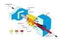
Aluminium extrusion is a plastic deformation process in which an aluminium billet is forced to flow by compression through the die opening. This openinng is a much smaller cross-sectional area than that of the billet.
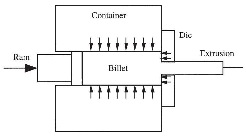 Figure 1
Depending on the design of the profile, the extrusion die can be solid, hollow or semi-hollow. However, any extrusion die has the bearings. The bearing is the last area of contact of metal with the extrusion die. This is where the profile takes its final shape. Figure 2 shows the bearing of a solid extrusion die.
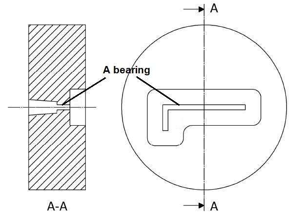
Figure 2
Figure 3 shows the bearings of hollow extrusion die.
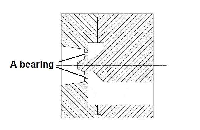 Figure 3
The reasons of uneven metal flow through a flat extrusion die can be the following. The frictional resistance at the billet/container interface slows down the metal flow near the billet surface. The center of the billet thus moves faster than the periphery of the billet. To balance the flow, bearing length must be inversely proportional to its distance from the center of the billet. The thinner the section, the slower the flow, due to the small die opening. Similarly, to balance the flow in the thinner section, the bearing length needs to be smaller, and vice versa.
The main methods for controlling the flow rate of aluminum through the bearing channel of a flat die are to do the following changes: the length of the parallel bearings, the angle of the bearings, and the size and shape of the prechamber.
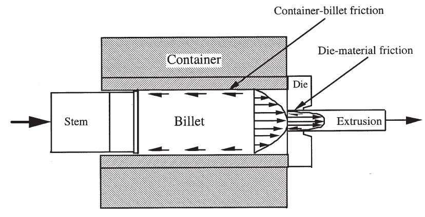 Figure 4
Figure 5 shows three types of bearings: parallel; choked to slow the flow; relieved to accelerate the flow.
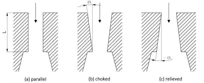 Figure 5
Parallel bearings are the working standard. In this case, the flow rate of aluminium through the working channel of the die is adjusted by changing the length of the bearings. Figure 6 shows the example of the control of the flow in an aluminium solid die using different lengths of bearings.
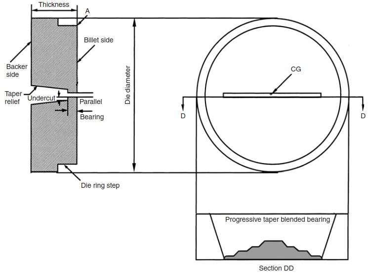 Figure 6
The methods of slowing and accelerating the metal flow trough the bearing channel shown in Figure 7. The view A shows choke at front of bearing to slow the flow. The view B shows relief at the back of the bearing to accelerate the flow.
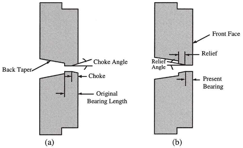 Figure 7
In Figure 8, the results of numerical simulation of the resistance of the bearing channel of the die, depending on the angle of the bearing are shown. The negative (relieved) angle gives low resistance to metal flow. With an increase of the relieved angle the flow resistance remains constant. When reducing the relieved angle for a small fraction of a degree to zero, that is before, as the bearing channel is parallel, the pressure increases dramatically.
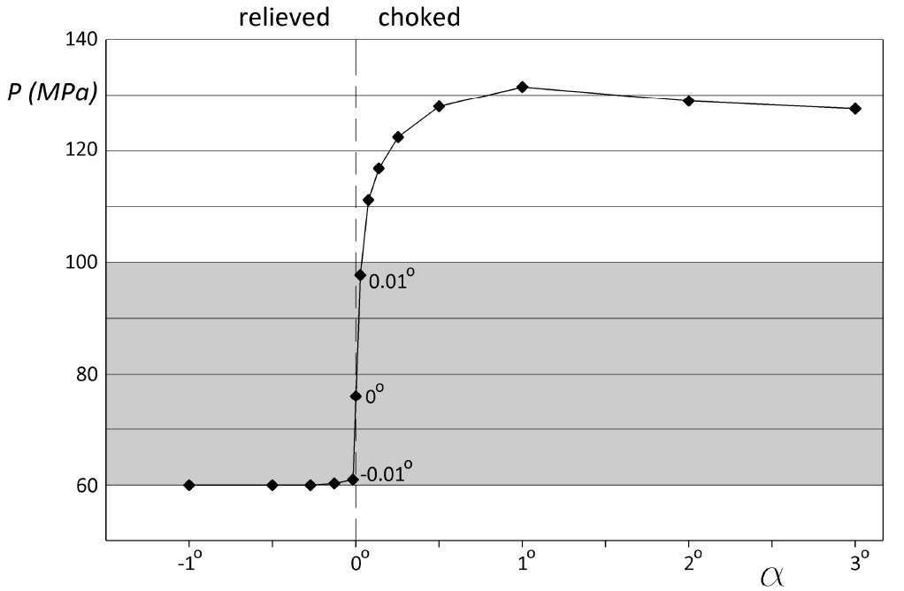 Figure 8
Such metal flow behavior can be explained as follows. In the accelerating (relieved) bearing channel, aluminium touches the walls of the bearing channel of the die only at its inlet and then loses contact with the bearings. The increase of the angle, and also the length of bearing, no longer influences the metal flow resistance of the bearing channel. The slowing (choked) bearing channel ensures the full contact of aluminium along the entire length of the bearing channel. A slight increase in the angle, at which there is full contact, almost no effect on the rate of flow of metal. The transition from almost no contact to the full contact occurs at the value of the angle about 0º.
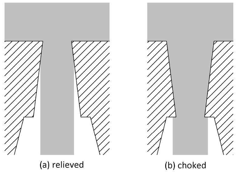 Figure 9
Sources: