Plasma Arc Welding of Aluminium
Principle of plazma arc welding
Thermal plasma consists of electrons, ions and neutral particles under high temperature and subject to a disordered violent movement. The molecules are partly dissociated and the atoms ionised. During collision with the work-piece surface, these give their energy up to the work and recombine.
The plasma is concentrated in the inside of the jet, thereby delivering a narrow plasma jet with a very high energy density. The plasma arc is, therefore, constricted and arcs between the tungsten electrode and the work-piece. The shielding gases used here are exclusively inert gases like argon, helium or a mixture of these gases. The tungsten electrode has a negative polarity and the work-piece a positive polarity (straight polarity).
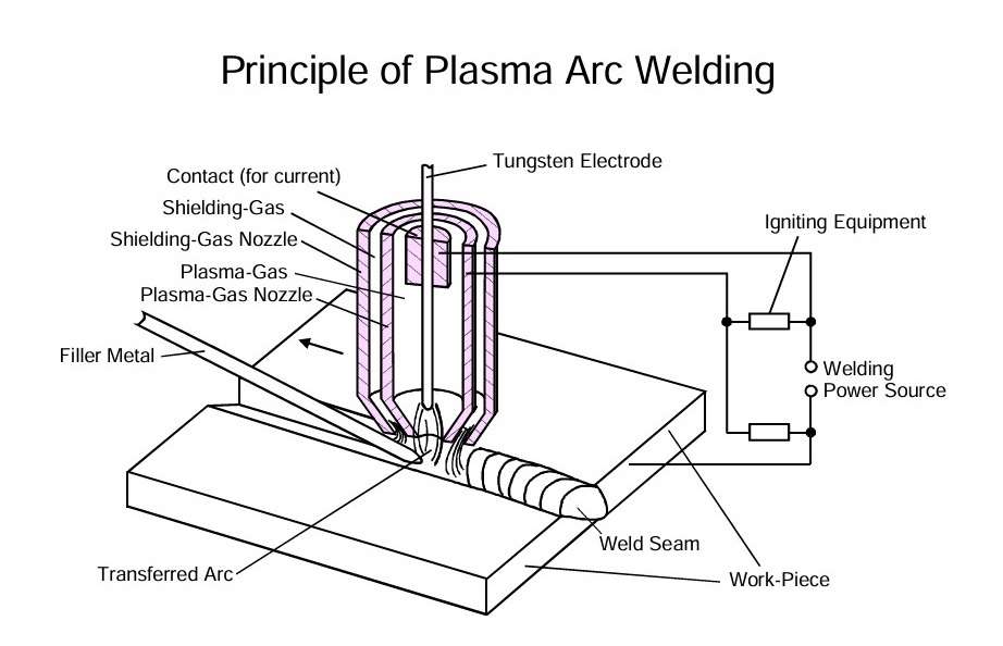 Figure 1 – Principle of plazma arc welding
Plazma arc compared to the TIG arc
Compared to the TIG arc, the constricted plasma arc has a much lower divergence, i.e., much larger changes in arc length can be tolerated. Thus, for example, a 20 % increase of arc cross-section corresponds to a ten times larger length of the plasma arc than of the TIG arc. This explains the relative insensitivity of the plasma arc to surface unevenness.
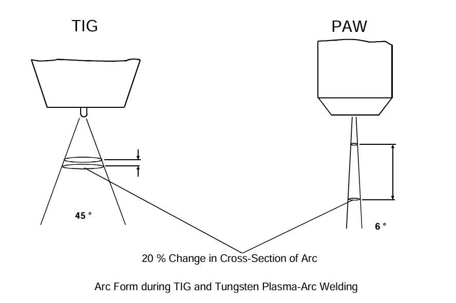 Figure 2 – Arc form during TIG and tungsten plazma-arc welding
Weld Pool Form and Heat Affected Zone
The ratio of penetration (weld depth) to weld width is twice as large for plasma arc welding as for TIG welding, making it possible to create narrow, deep weld profiles. Consequently, thicker sheets can be welded using square butt joints. The amount of filler metal and the heat input is much lower, so that distortion is less and heat sensitive materials can be better controlled. The overhead shows a plasma arc weld with a “wine glass” type of weld penetration.
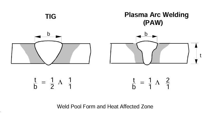 Figure 3 – Weld pool form and heat affected zone
The bundled and strongly constricted plasma stream is stabler than in the TIG process. The plasma arc does not tend to “stick” to edges and the weld pool.
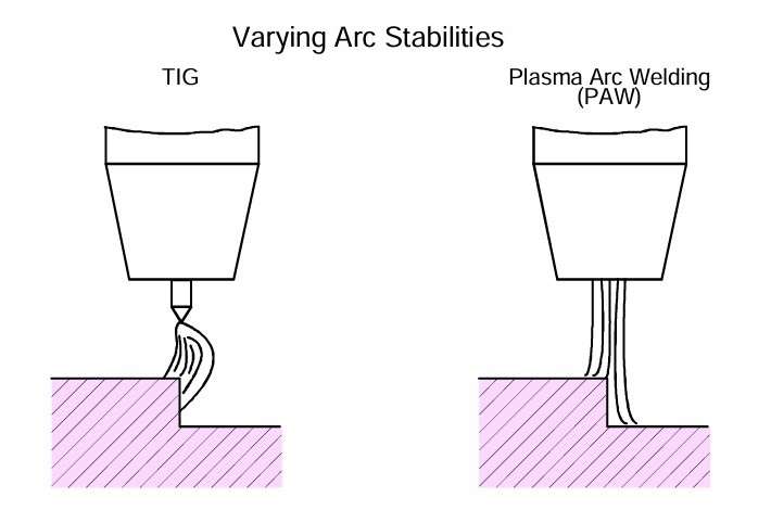 Figure 4 – Varying arc stabilities
Variants of Plasma Arc Welding
Plasma Arc Welding has several variants depending on the polarity graph of electrode, for example, Positive Polarity and Variable Polarity. Guide Values for the Positive Polarity Plasma Arc Welding are shown in this figure. Because of the excessive heat produced at the positively poled electrode, the current strength should be limited to a maximum of about 170 A. Currents of up to 300 A can be used for water-cooled copper electrodes.
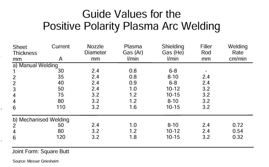 Figure 5 – Guide values for the positive polarity plazma arc welding
The Variable Polarity Plasma Arc (VPPA) welding is mostly carried out in the welding position PF (vertical upwards).
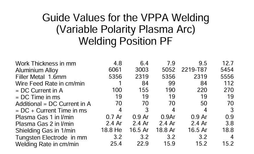 Figure 6 – Guide values for the variable polarity plazma arc welding. Welding position PF
The source:
TALAT Lecture 4201 – Arc Welding Processes: TIG, Plasma Arc, MIG / Ulrich Krüger – European Aluminium Association – 1994.