Gas Porosity: An Aluminium Casting Defect
Solidification defects in aluminium castings
Solidification defects in castings can be sub-divided into three main categories:
- Gas porosity.
- Shrinkage porosity.
- Hot tearing and cracks.
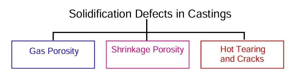 Figure 1 – Solidification defects in castings
Gas porosity
In this post, we will consider gas porosity in aluminium castings.
Gas Porosity can again be sub-divided into a further three causes:
- Firstly, gas held in solution in the molten metal can be precipitated as the metal solidifies, simply as a result of the reduced solubility on freezing.
- Secondly, if the mould is filled under very poor conditions, air can be entrained in the metal stream and then trapped as the metal solidifies.
- Finally, the sand binders used to make the moulds and cores often break down when in contact with the molten metal and the gaseous decomposition products can force their way into the solidifying metal, leading to defects which are normally known as ‘blows’.
These different types of gas porosity defect vary in their size, distribution, distance below the casting surface and morphology.
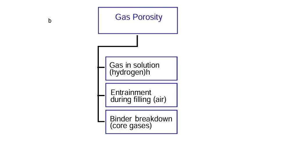 Figure 2 – Types of gas porosity defects in castings
Gas in solution
The first type of gas defect is caused by precipitation of gas from solution in the liquid metal. In the case of aluminium, it is particularly concerned about hydrogen. The sources of hydrogen in castings are shown in this figure. The main sources of hydrogen are melting and subsequent handling of aluminium and burning hydrocarbon fuels, such as gas or oil, in melting and holding furnaces.
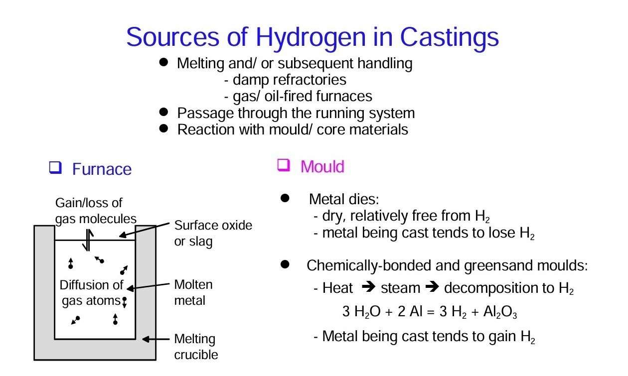 Figure 3 – Sourcrs of hydrogen in castings
Hydrogen porosity
Gas precipitation from solution in the metal leads to small bubbles, normally in the size range 0,05 – 0,5 mm. It is a result of the high internal pressure of gas due to the microsegregation between the dendrite arms. The bubbles are distributed uniformly throughout the casting, with the exception of a bubble-free surface layer about 1 – 2 mm deep. Figure 4 shows a typical example of hydrogen bubbles in a simple aluminium casting and emphasises the size and distribution characteristics.
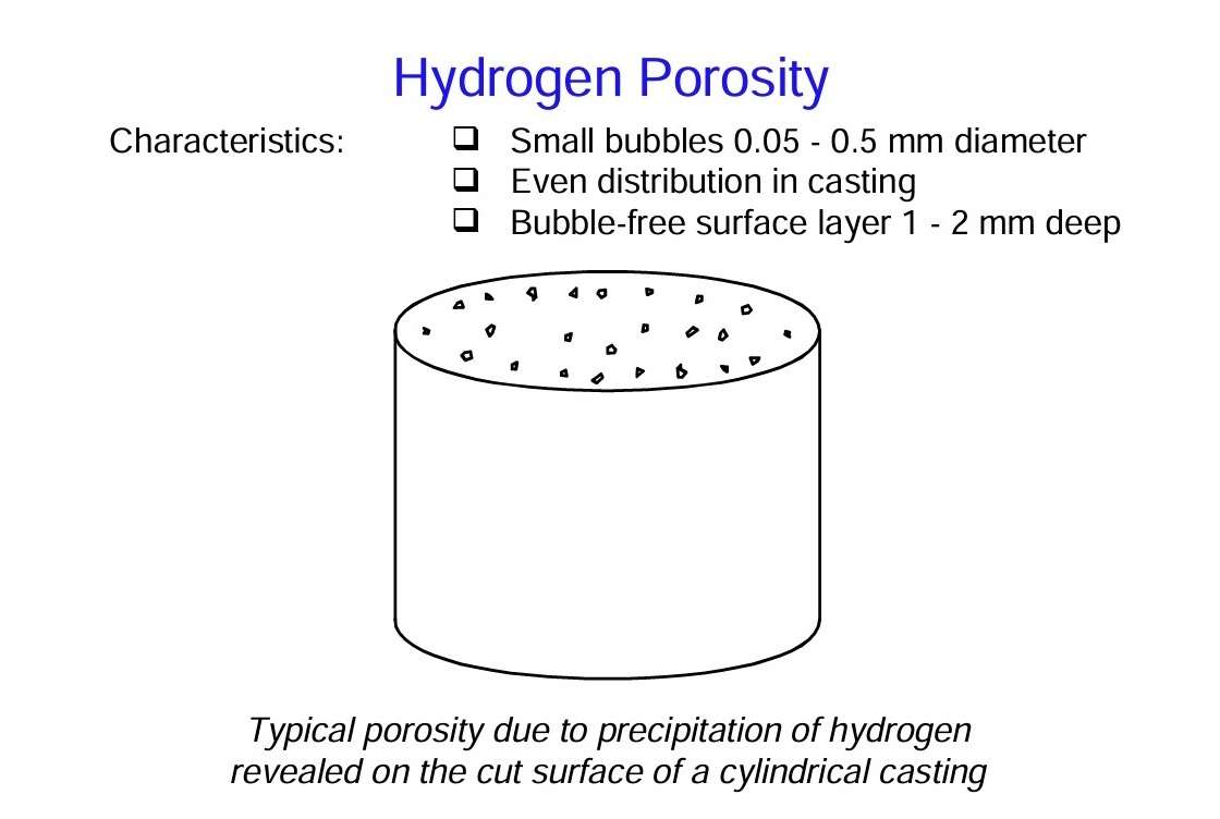 Figure 4 – Hydrogen porosity
Hydrogen precipitation
Figure 5 shows a schematic view of a section through a solidifying casting with the mould on the left-hand side, a solidified layer about 1 – 2 mm thick which is free from gas bubbles, and then the dendritic growth front. As further growth of the dendritic front occurs, we find that small hydrogen gas bubbles are precipitated and become trapped in the dendrite forest.
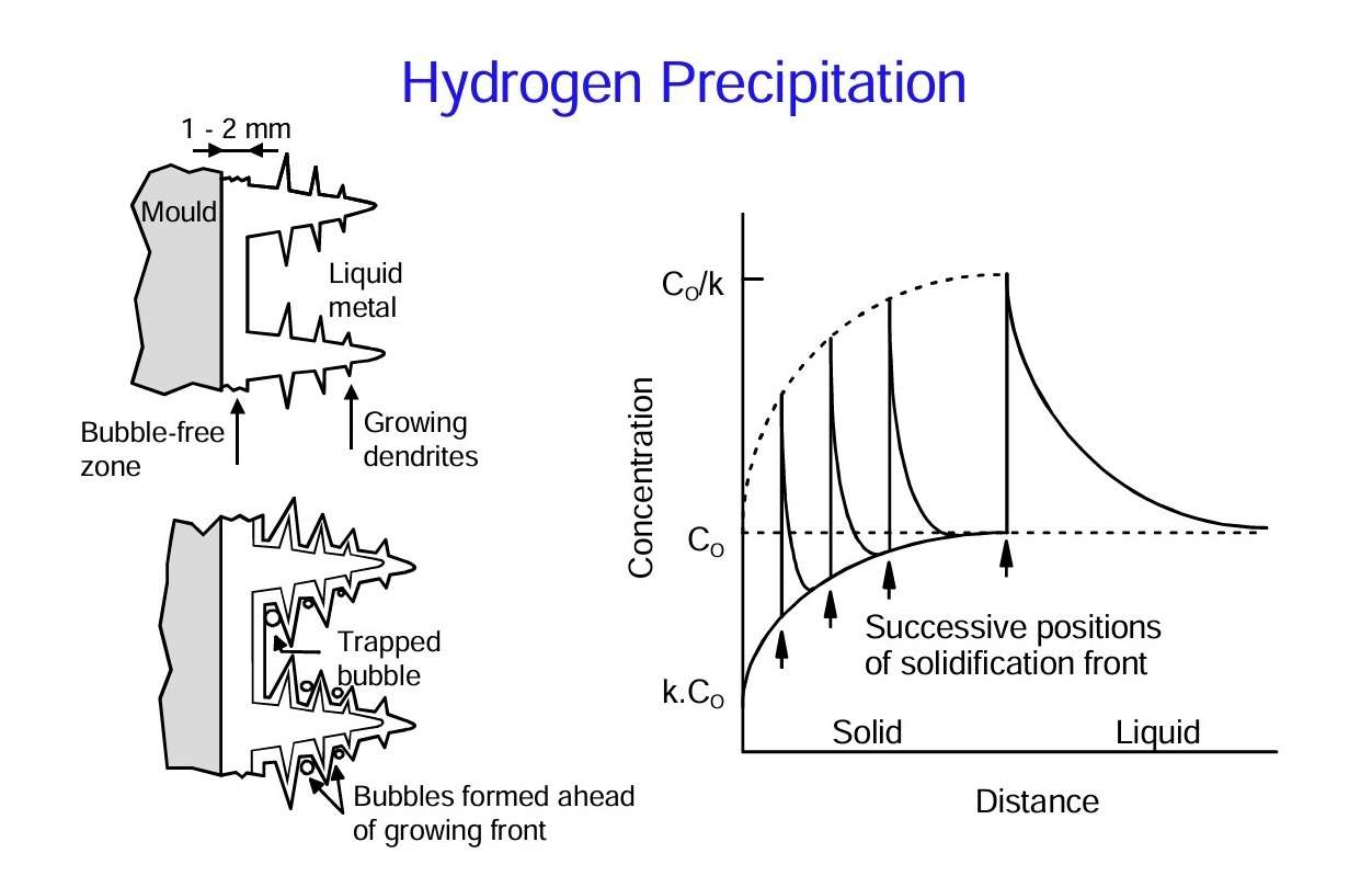 Figure 5 – Hydrogen precipitation
Hydrogen in molten aluminium
Figure 6 shows the behavior of hydrogen in molten aluminium. Solidification leads to an increase in the amount of hydrogen dissolved in solution of 20 times. Thus if the initial gas content is 0,1 ml/100 g, which is not particularly high, the hydrogen content at the interface would be 2 ml/100 g once steady state is reached. This value is above the solubility limit and thus the liquid aluminium is supersaturated with hydrogen.
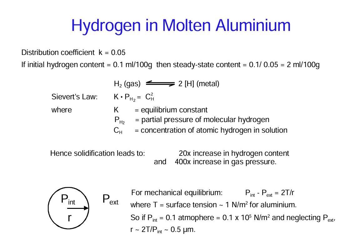 Figure 6 – Hydrogen in molten aluminium
The final point about gas porosity is that nucleation of gas bubbles continues as metal continues to solidify. This leads to an even distribution with the exception of 1 – 2 mm at the surface of the casting.
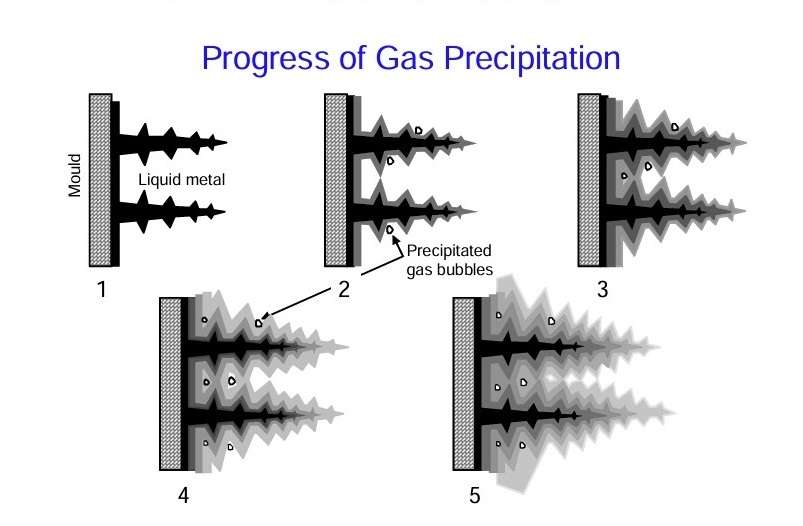 Figure 7 – Progress of gas precipitation
Air entrainment
Now let’s move on on to the entrapment of air. An example is a sump casting that has been deliberately made badly using a conical pouring basin, a parallel downsprue and no well base. In addition, we have a non-tapered runner bar and insufficient gates. Such a running system generates surface turbulence in the metal stream as it fills the mould, leading to a chaotic, scrambled mess of metal and air. The air cannot escape easily because it is held in place by the oxide film. Furthermore, as the air bubbles move through the molten metal, they leave behind a collapsed sac of oxide, forming a bubble trail which is another form of defect in the casting.
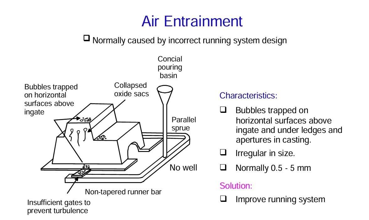 Figure 8 – Air entranment in castings
Gas coming from cores
Now let’s consider the third gas porosity defect: gas coming from cores. The final type of gas defect is blown from cores. When a metal is poured into a sand mould containing cores, the gas present in the core expands and attempts to escape. Furthermore, the resin binders used in core manufacture start to break down and generate additional gas. The gas can escape from the core via the core prints, but if the core prints are too small or if the mould and core have a low permeability, the gas pressure will build up inside the core. If the pressure reaches the level where it exceeds the opposing pressure of the molten metal, a bubble can be formed in the metal and float up towards the top of the casting.
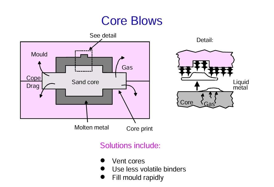 Figure 9 – Core blows
The minimum thickness of the bubble in a liquid aluminium alloy when lodged under a horizontal flat surface is usually approximately 12 mm. This dimension is controlled by the ratio of surface tension and density. The diameter of the bubble can of course be any size, depending on the amount of gas released by the core, and is typically 10 to 100 mm.
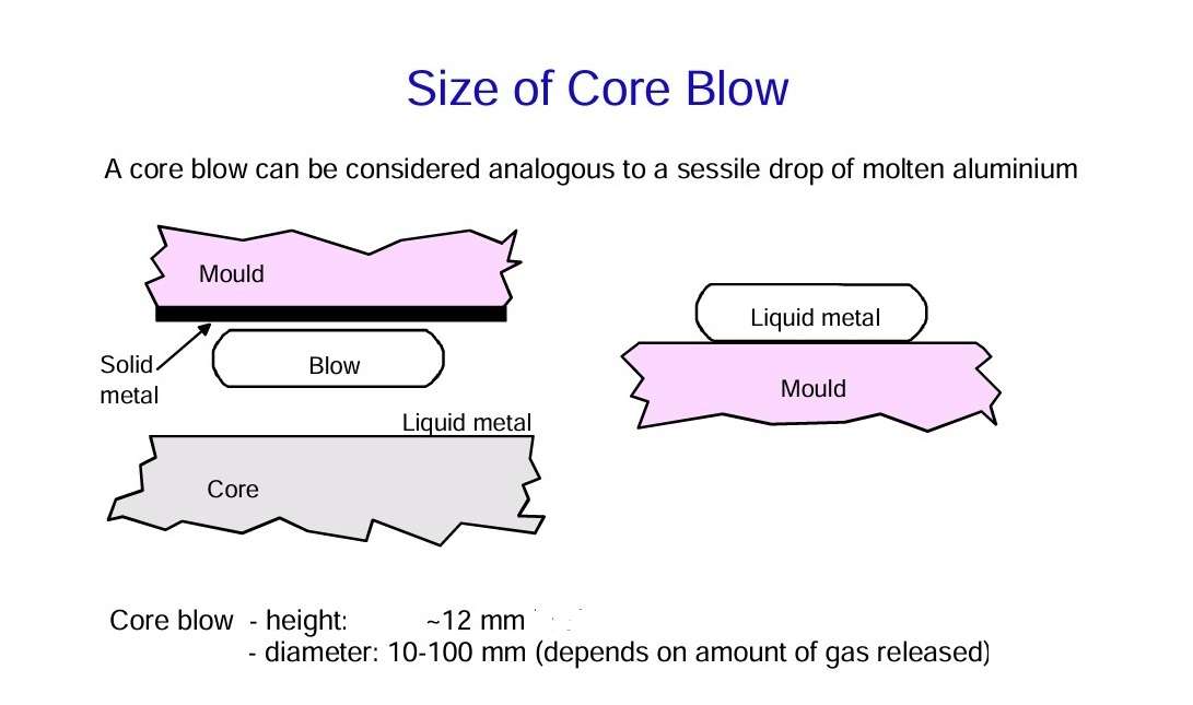 Figure 10 – Size of core blow
Characteristics of gas porosity defects
Figure 10 summarises the various gas defects and emphasises that they differ significantly in distribution and size. It is most important to bear such differences in mind when trying to diagnose defects in castings, because, clearly, the remedies will be very different in each case.
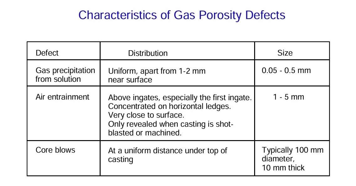 Figure 11 – Characteristics of gas porosity defects
The source: