Extrusion Press Alignment: Tools and Technique
Proper extrusion press alignment is mandatory for maximizing production quality, reducing structural component wear, and minimizing unplanned downtime. The strict geometric relationships of both static and moving press components form the foundation of precise operation.
These geometric tolerances must remain correct when the machine reaches its operational working temperature to account for complex thermal growth effects. They must also withstand dynamic mechanical stresses during operational load cycles, including intense container sealing pressures and high-tonnage forward ram displacement.
Identification of Extrusion Press Components
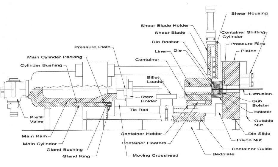
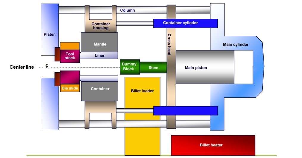
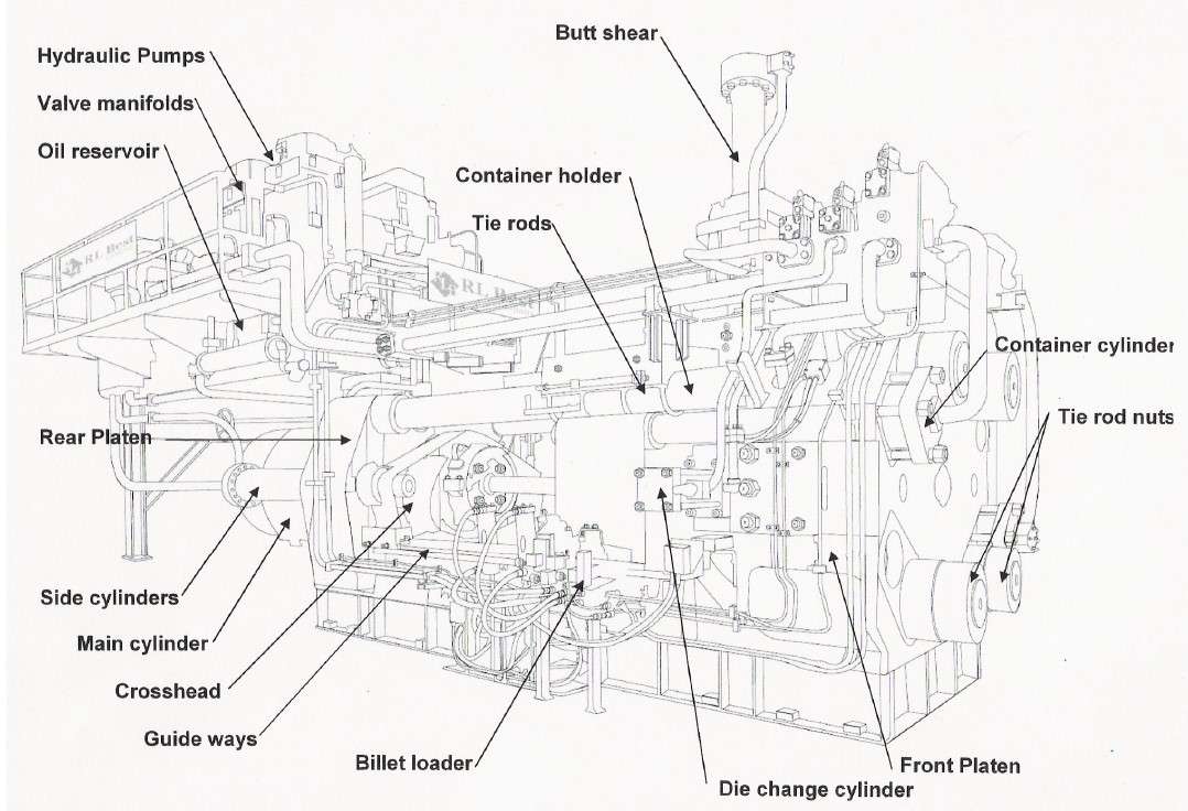
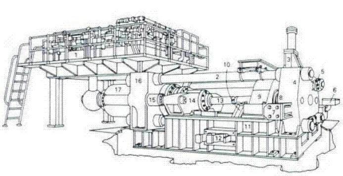
- 1 – Hydraulic Power Unit: Supplies pressurized fluid to main and auxiliary cylinders.
- 2 – Tie Rods (Columns): Absorb the massive structural tension forces during extrusion.
- 3 – Butt Shear: Cuts off the unextruded billet scrap from the die face.
- 4 – Extrusion Platen (Front Platen): Holds the tool stack securely against extrusion forces.
- 5 – Container Shifting Cylinders: Move the container back and forth to seal against the die.
- 6 – Operator’s Console: The primary human-machine interface controlling all sequences.
- 7 – Die Slide: Transports tool stacks into and out of the center line.
- 8 – Container: Houses the liner where the heated aluminum billet is compressed.
- 9 – Container Housing: Structurally supports the container and its integrated heating elements.
- 10 – Billet Loader: Receives and lifts the hot billet into the press centerline.
- 11 – Press Base: Heavy steel frame anchoring all components to the foundation.
- 12 – Billet Loader Cylinders: Actuate the physical lifting arm mechanics of the loader.
- 13 – Pressing Stem: Transmits the physical ram force directly to the billet face.
- 14 – Crosshead: Moving block driven by the main ram that carries the stem.
- 15 – Side Cylinders: Provide high-speed advance and retraction of the main crosshead.
- 16 – Cylinder Platen (Back Platen): Rigidly holds the main hydraulic extrusion cylinder assembly.
- 17 – Main Cylinder: Large-bore cylinder generating the high-tonnage primary extrusion force.
Geometric Alignment Requirements
1. Static Components
- Base Plate Flatness: Must be perfectly level with all support contact spots resting in an absolute flat plane.
- Platen Perpendicularity: Both front and back platens must stand perfectly perpendicular relative to the base.
- Pressure Ring Coaxiality: Front platen hole bushing must be centered and parallel to the main platen face.
- Press Centerline Uniformity: All platen-centered cavities must coincide precisely on a single theoretical center axes line.
- Guideway Parallelism: Crosshead and container ways must remain straight and symmetrically spaced around the centerline.
- Main Cylinder Concentricity: Cylinder sleeve, bearing flanges, and ram piston must be completely concentric to the back platen.
- Stem True Squareness: Crosshead-mounted extrusion stem must stand strictly perpendicular relative to the back platen face.
- Tie Rod Symmetry: Geometric axes of all four columns must run perfectly parallel and equidistant from the press center.
2. Moving Components
- Ram Stroke Linearity: Ram piston and extrusion stem must track the true press centerline across their entire stroke length.
- Container Bore Concentricity: Internal liner bore centerline must remain perfectly coincident with the press axis from open to sealed state.
- Tooling Stack Alignment: Die assembly centerpiece centerline must remain completely concentric under active high-pressure extrusion loads.
- Billet Loader Concentricity: Lifting arm must position the raw billet axes identically to the container and stem axes before loading.
Traditional vs. Modern Metrology Methods
Methods for extrusion press alignment and metrology instruments are broadly divided into traditional (one-dimensional) and modern (three-dimensional) categories.
Traditional techniques rely on linear, step-by-step isolated measurements. While reliable for routine single-component field checks, a comprehensive alignment using traditional tools is incredibly time-consuming (often taking several days). This is because multiple assemblies must be completely unmounted, and measurements can typically only be performed when the press is entirely cold.
Conversely, modern 3D coordinate-measuring systems (such as Laser Trackers) offer a global, non-contact approach. They deliver significantly higher data precision, eliminate structural disassembly, and dramatically minimize machine downtime. Crucially, laser systems allow engineers to audit structural deformation and thermal growth anomalies at real operational working temperatures.
Traditional Alignment Methods and Tools
1. Machinist’s Precision Level
- Resolution Level: Offers an accuracy of 0.004 mm/m.
- Operational Constraint: Strictly cannot be applied to hot surfaces due to fluid-bubble thermal expansion errors.
2. Surveyor’s Precision Optical Level
- Resolution Level: High-accuracy optical sights reaching 0.001 mm/m.
- Primary Function: Historically utilized for long-distance horizontal baseline tracking and foundation leveling.
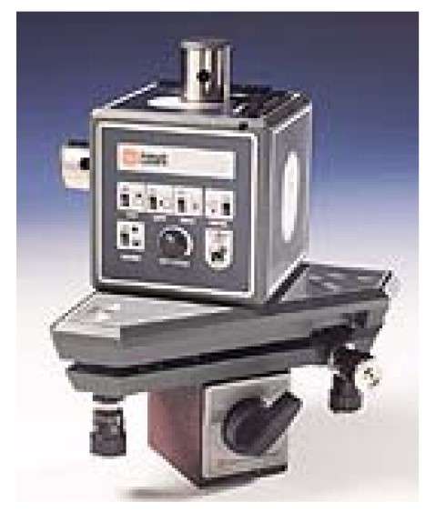
3. Three-Plane Laser Level
Commonly replaces classic surveyor levels to establish continuous geometric baselines across multiple axes simultaneously.
4. Custom Trammel Rod
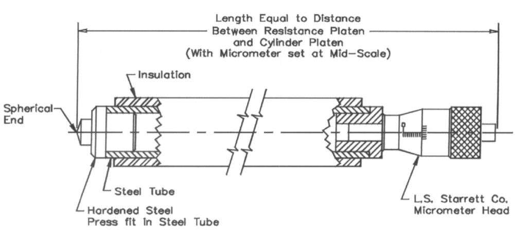
- Fabrication Type: Custom-built rigid metal tubing customized to specific machine dimensions.
- Component Design: Steel or aluminum pipe equipped with a precision micrometer head on one end and a polished spherical contact tip on the other.
- Deflection Safeguards: Features specialized rigid structural support fixtures to eliminate gravity-induced pipe sagging.
- Thermal Insulation: Coated in specialized protective layers to prevent localized structural expansion caused by residual container heat.
- Target Task: Accurately tracks changing face-to-face distances between large crossheads or structural column bushings.
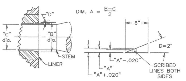
5. Taper Gauges
Mechanical wedge-style tools utilized to quickly assess clearance gaps, face wear, and structural parallelism on container sealing surfaces.
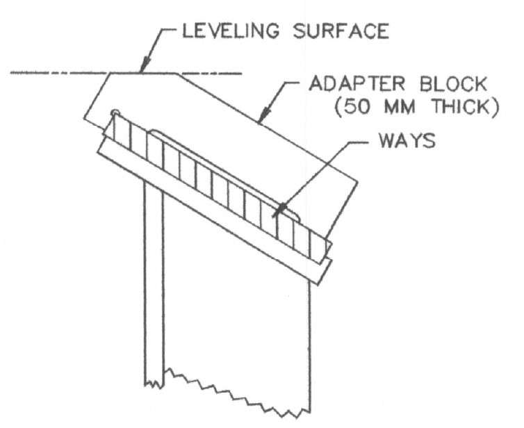
6. Adapter Block for Angled Guideways
- Structural Solution: Tailored adapter fixtures machined for presses engineered with non-horizontal, sloped guideway rails.
- Primary Function: Converts sloping geometry back into standard horizontal baselines, allowing standard precision levels to be deployed flawlessly.
7. Piano Wire Method
- Wire Specifications: High-tensile carbon steel wire featuring a precise diameter of 0.4 to 0.5 mm.
- Material Strength: Rated for extreme mechanical tension loads between 1700 and 3400 N/mm².
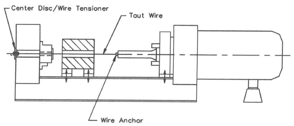
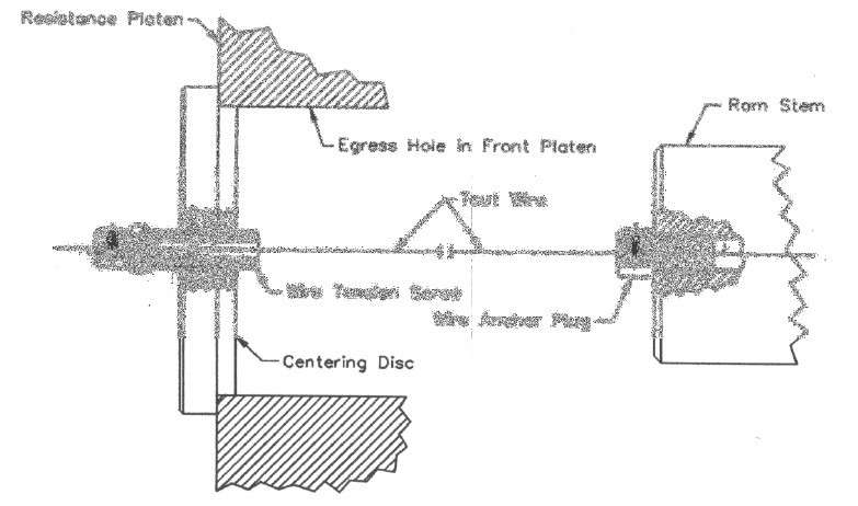
8. Fixtures for Piano Wire Tensioning
Determination of the press centerline via the piano wire method requires stretching the wire under extreme tension between the center of the front platen bore and the main cylinder extrusion stem face.
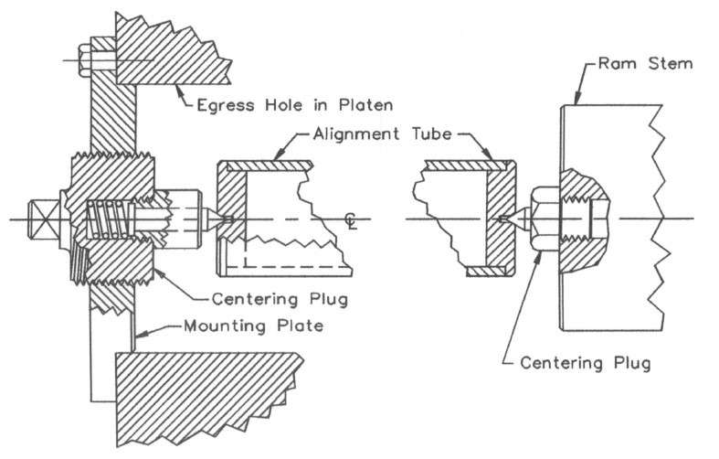
9. Precision Tube Fixture
As a more rigid alternative to stretched wires, this setup utilizes an ultra-straight, precision-ground heavy tube assembly fitted with customized end plugs and self-centering target adapters.
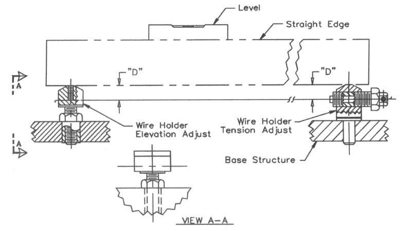
10. Base Centerline Fixtures
Achieves global alignment referencing by tracing the extrusion press bed centerline via dedicated master alignment indexing holes pre-machined directly into the lower frame base structure.
References
- Extrusion Press Maintenance Manual, ed. Al Kennedy.
[Available as a free online living reference at PressManual Online; see also author updates via Al Kennedy on LinkedIn]. - “Extrusion Press Alignment with Modern Technology,” J. E.V. Mulder and G.J. Smith – Aluminium Extrusion Seminar.
[Full technical paper available via A-Solution Metrology Documentation]. - Aluminum and Aluminum Alloys, ASM Specialty Handbook – 1996.
[Reference details and purchase catalog available via Amazon Books and chapter indexing on the ASM Digital Library]. - “Influence of Al Microstructure on Hard Anodising Quality – Profile Material,” Tom Hauge, Hydro Aluminium, Norway – 2014.
[Original seminar presentation guidelines available via Luke Engineering Technical Archives].

