Aluminium extrusion die corrections
Die corrections could be required due to many reasons, such as:
- improper metal flow
- dimensional variation
- surface finish
- improper interference with runout table
Many factors affect the running of a die at the press. These factors need to be considered when correcting extrusion dies:
- die temperature
- billet temperature with respect to container temperature
- taper billet heating
- change of extrusion speed
- press alignment and adjustment
- deflection of die stack
- rotating the die to change position
In addition, problems associated with the press can include the following:
- improper tool stack,
- flatness of the pressure ring,
- improper sealing of the die with the container liner,
- a washed out container liner, and
- worn out dummy pads.
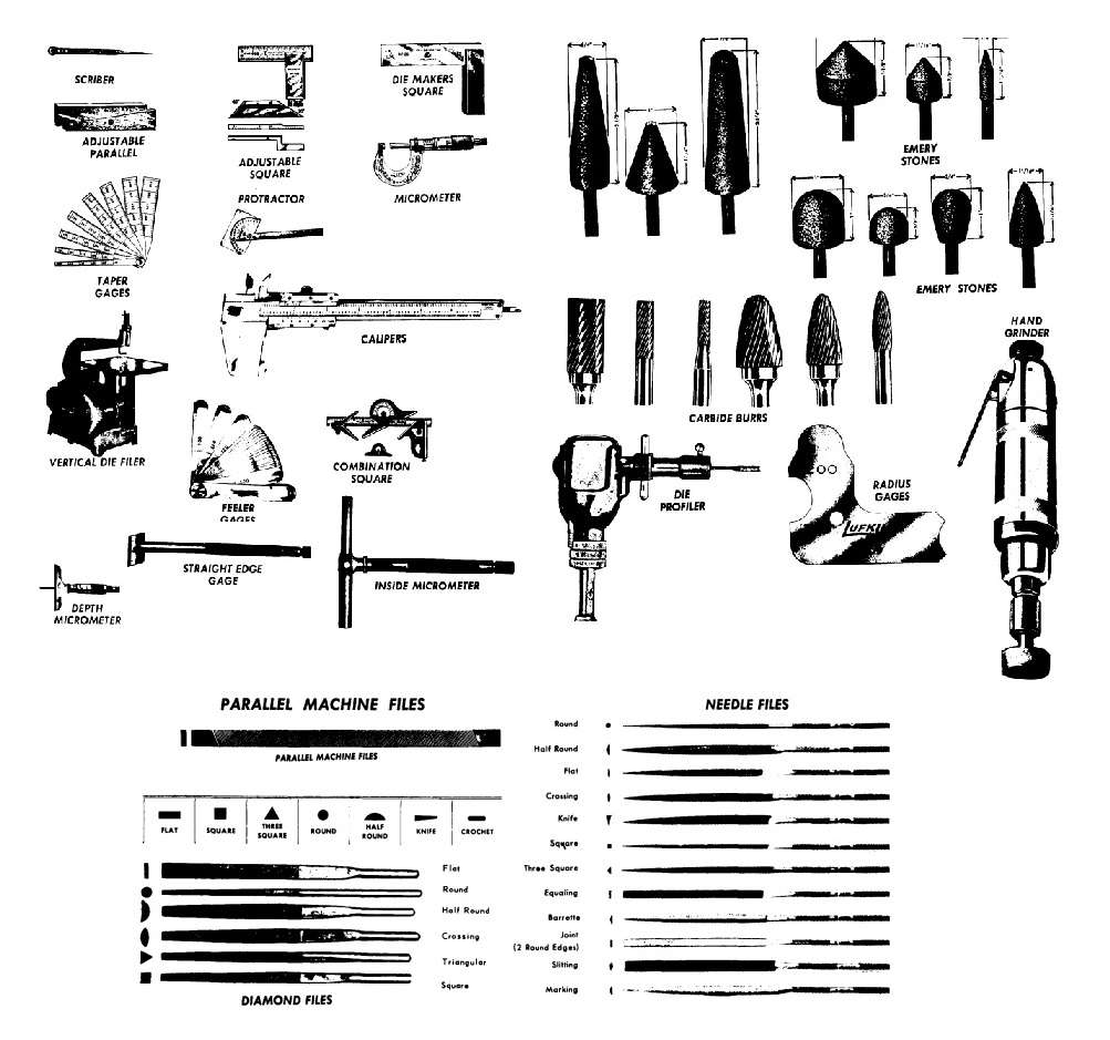
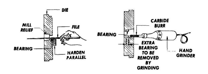
Some of tools used in the dayly work of any corrector are illustrated in Figure 3.
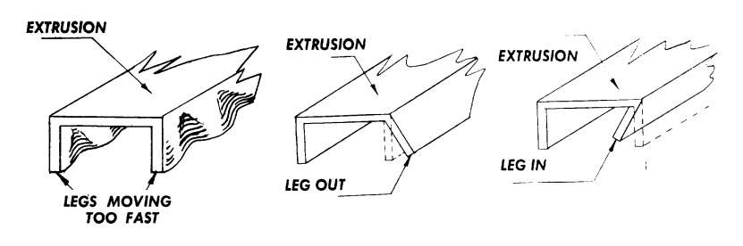
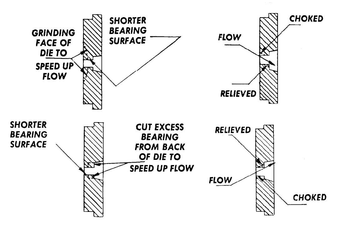
Examples of improper metal flow through a flat die are shown in Figure 4.
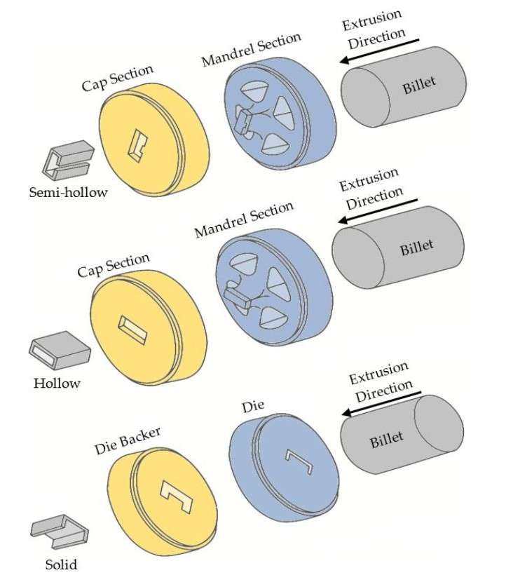
Correction of a solid die can require:
- modification in the pocket
- modification the feeder plate
- modification of the bearing length from the front or exit side of the die
The proper method of correction should be by using:
- a milling machine
- a flexible grinder,
- an old carbide-tipped method.
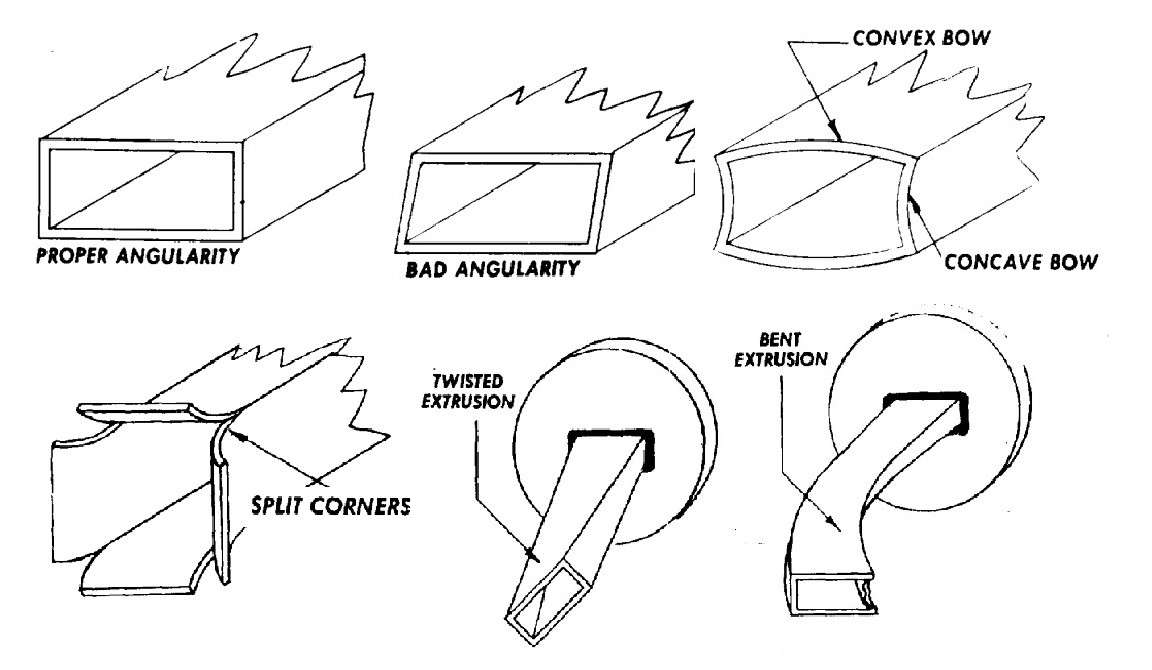
The correction of a hollow die is very complex compared to that of a solid die, because the aluminum is flowing through three stages, as shown in Fig. 21. There are many variables associated with hollow dies such as ports, depth of bridge, and the weld chamber cavity. The correction of hollow dies could be due to:
- twist,
- angularity,
- split corners,
- a convex wall,
- a concave wall, and
- an uneven wall.
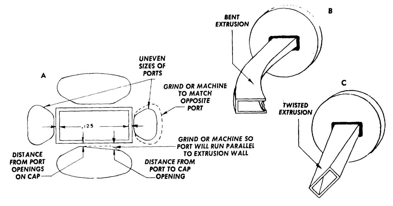
To correct the flow on a hollow die, examine the port first before working on the bearings. Ports control the volume of metal, which needs to be balanced in relation to the cross-sectional area of the extrusion that each port is feeding.
The sources:
1. P. Saha, Aluminum Extrusion Technology, 2000
2. Die Defects and Die Corrections in Metall Extrusion / S. Z. Qamar, T. Pervez and J. Ch. Chekotu, Metals, 2018, 8, 380
3. Practices, Problems and Corrective Measures in Extrusion Press Tooling / H. Glicken & Luis Bello // Aluminum Extrusion Technology Seminar, Chicago, 1977
4. Die Corrections For Changing Flow Characteristics / Luis Bello // Aluminum Extrusion Technology Seminar, Chicago, 1977
Watch this on YouTube: https://youtu.be/FBSd1WNV5n4

