Aluminium Casting Design Guidelines
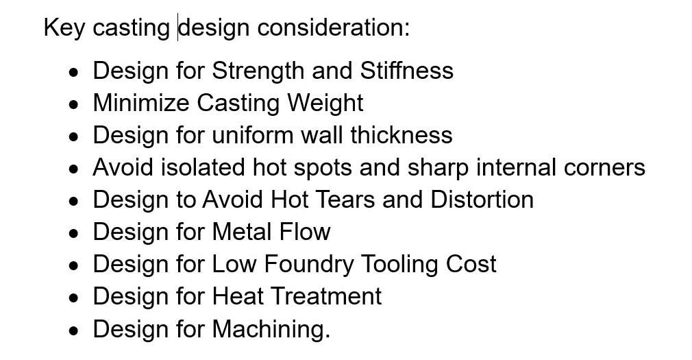
Key casting design considerations
Casting design, including aluminium casting design, involves the specification of the overall configuration of the casting as well as the detail geometry of the various features that comprise it. The goal of casting design is:
- First, satisfy the functionality and service requirements of the application.
- Second, specify a casting configuration and detail design that results in low cost, high inherent quality, and short lead time.
Key casting design considerations are shown in Figure 1.
Figure 1 – Key casting design considerations
Design for Strength and Stiffness
The strength and stiffness of the casting will be maximized by locating material where it is needed while avoiding unnecessary bulk and weight. Figure 1 illustrates the importance of metal distribution on the load carring capacity of a beam. All four sections have the same area and weight, and all exept the round shapehave the same width and height. Note that the cross and round sections have only about 50 percent of the rigidity of the I-beam.
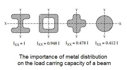 Figure 2 – The imortance of metal distribution
Minimize Casting Weight
Weight of the casting can be reduced by designing the casting by utilizing a minimum uniform wall thickness everywhere in the casting. There are a variety of design approaches to use of thinner walls, for example, the use of ribs as shown in Figure 3.
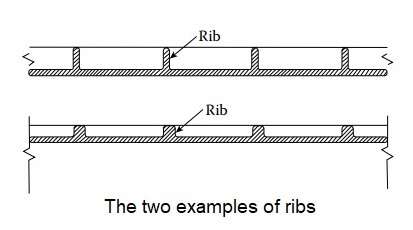 Figure 3 – The two examples of castinng ribs
Design for uniform wall thickness
When heavy sections cannot be avoided, then risers or other costly foundry remedies must often be used. A far preferable approach is to avoid heavy sections by designing the casting to have a uniform wall thickness as it is shown in Figure 4.
 Figure 4 – Design for uniform wall thickness of a casting
Avoid isolated hot spots and sharp internal corners
The corners of all intersections and junctions should have fillet radii. The size of the fillet radii used must often strike a balance between stress concentration and the possibility of a hot spot. The small filler radius inhibite the flow of molten metal during filling and also can cause cracking during cooling or use of the casting.
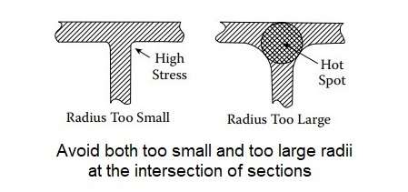 Figure 5 – The avoidance of both too small and too large radii at the intersection of sections
If the fillet radius is made too large, isolated hot spots can occur because the metal mass at the intersection will be larger than the features that are joined. The casting designer should therefore specify corner radii that are neither too large or too small to insure that both of these undesirable effects are avoided.
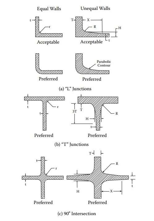 Figure 6 – The specifying of corner radii
Often the best choice will depend on the particular alloy. For example, alloys that exhibit little solidification shrinkage are typically not sensitive to junction design.
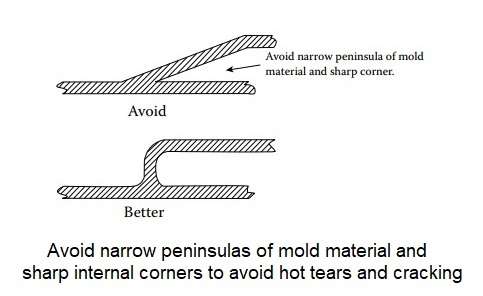 Figure 7 – The avoidance of narrow peninsulas of mold material and sharp internal corners
Design to Avoid Hot Tears and Distortion
As the casting solidifies and cools, it shrinks. If the mold walls and/or cores inhibit or constrain this shrinkage, internal stress will develop. This can result in hot tearing or cracking if the stress exceeds the strength of the alloy or the stress may be “frozen in” as residual stress causing distortion and warpage of the casting when it is removed from the mold and/or when it is machined.
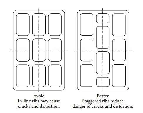 Figure 8 – The avoidance of distorsion and warpage of the casting
Similar effects will occur if different sections of the casting cool at different rates or if the distribution of metal is asymmetric. The best way to avoid hot tears and distortion is to avoid asymmetrical distributions of metal and to use a uniform wall thickness everywhere.
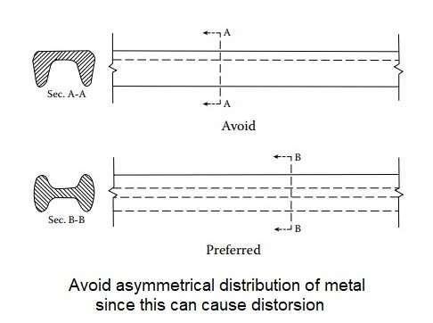 Figure 9 – The avoidance of asymetrical distribution of metal
When this is not possible, transitions to different section thickness should be carefully designed so that the degree of constraint imposed on the solidifying casting is minimized.
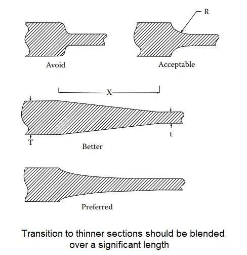 Figure 10 – Transition to thinner sections
Design for Metal Flow
Misruns and cold shuts occur when the molten metal solidifies prematurely in crosssections that are too long and narrow or that are too thin. Alloys having poor or fair fluid life require thicker sections than those having good to excellent fluid life.
 Figure 11 – Design for metal flow
Design for Low Foundry Tooling Cost
Every opportunity should be taken to minimize casting complexity and promote ease of fabrication.
 Figure 12 – Disign for low foundry tooling cost
Design for Heat Treatment
Guidelines for achieving a heat-treatment friendly casting design are shown in this figure. When these guidelines cannot be followed, the designer is
advised to consider the selection of an alloy that is suitable for lower temperature aging-only heat treatment or an alloy that is self-aging.
 Figure 13 – Design for Heat Treatment
Design for Machining
- Reduce the volume of material to be removed.
- Minimize the size of surfaces to be machined.
- Specify alloys and heat treatments that result in good machinability.
- Avoid tight tolerances.
- Avoid excessively smooth surfaces.
- A minimum number of machining setups and operations.
- All machining is performed on ortogonal and/or parallel surfaces.
- All processing in one direction cfn be completed before moving to the next.
- Insure access to surfaces that are to be machined.
- Provide clearance for tool.
- Specify features such as fillet radii that allow shorter tool path lengths.
- Use standardized features; avoid non-standard features.
- Avoid sharp angles, edges, and corners as these features typically cool faster resulting in harder to machine material properties.
- Minimize the number of machining directions as it shown in Figure 14.
 Figure 14 – Approaches for simplifying the machining of a casting
The source:
Casting Design / Henry W. Stoll // Encyclopedia of Aluminum and Its Alloys – Edited by George E. Totten, Murat Tiryakioğlu, and Olaf Kessler – 2019
