TIG welding of aluminium
Learn about the process of TIG welding of aluminium and its applications in joining metal components. Discover the different types of fusion welding techniques.
TIG welding of aluminium
Tungsten arc inert gas shielded welding is an arc welding process that uses a non-consumable tungsten electrode and an inert gas shield to protect the
electrode, arc column and weld pool, as illustrated in Figure 1.
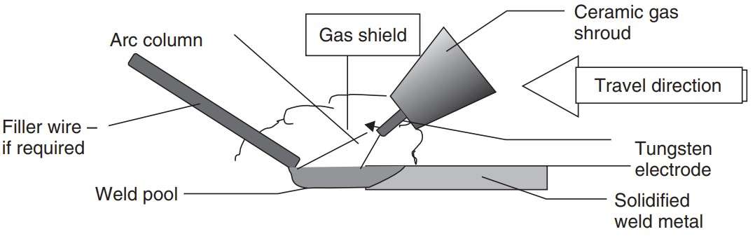 Figure 1 -The arc welding process in an inert gas atmosphere with tungsten electrode [1]
Three designations are used for this welding process: TIG, TAGS и GTAW. The first two are mainly used in Europe, the third – in the US. These designations are abbreviations of various process items, which are various combinations of the first letters of the following keywords:
- T: Tungsten
- I: Inert
- G: Gas
- S: Shielding
- W: Welding
- A: Arc.
Below, for brevity and convenience, we will call this process: the TIG welding of aluminium.
The characteristics of TIG welding of aluminium
- The welding arc acts as a heat source only.
- The welder has the choice of whether or not to add a filler wire.
- The weld pool is easily controlled such that unbacked root passes can be made
- The arc is stable at very low welding currents enabling thin components to be welded
- The process produces very good quality weld metal, although highly skilled welders are required for the best results.
- It has a lower travel speed and lower filler metal deposition rate than MIG welding, making it less cost effective in some situations.
- TIG tends to be limited to the thinner gauges of aluminium, up to perhaps 6 mm in thickness.
- It has a shallower penetration into the parent metal than MIG and difficulty is sometimes encountered penetrating into corners and into the root of fillet welds [1].
Equipment for TIG welding of aluminium
The basic equipment for TIG welding comprises:
- a power source,
- a welding torch,
- a supply of an inert shield gas,
- a supply of filler wire and perhaps
- a water cooling system.
A typical assembly of equipment is illustrated in Figure 2.
 Figure 2 – Manual DC-ve TIG welding repair of aluminium castings using
helium shielding gas (Courtesy of TPS-Fronius Ltd) [1]
TIG welding: DC or AC
For welding most materials the TIG process conventionally uses direct current with the electrode connected to the negative pole of the power
source. Welding on this polarity does not give efficient oxide removal. A further feature of the gas shielded arc welding processes is that the bulk of the heat is generated at the positive pole [1].
TIG welding with the electrode connected to the positive pole results in overheating and melting of the electrode [1].
Manual TIG welding of aluminium is therefore normally performed using alternating current, AC, where oxide film removal takes place on the electrode positive half cycle
and electrode cooling and weld bead penetration on the electrode negative half cycle of the AC sine wave. The arc is extinguished and reignited every half cycle as the arc current passes through zero, on a 50 Hz power supply requiring this to occur 100 times per second, twice on each power cycle [1].
Shielding gas
Argon
The preferred shielding gas for AC-TIG welding is argon.. Helium, and mixtures of argon and helium may also be used. Argon provides a broad and deep penetration of the weld, and thus makes the weld shiny and silvery. The easiest and most ignition and stable arc is achieved with the use of argon.
Helium
Helium increases the arc voltage, increases weld penetration depth, but makes ignition more difficult, but also adversely affects the arc stability. Some modern welding machines have the ability to start welding with argon and then, when the arc established, automatically skips helium.
Argon + Helium
The addition of argon to helium improves the ignition and its stability. The welding speed and penetration weld will be less, than when welding with a pure helium, but better, than when welding with argon only. Therefore it is possible to adjust seam width and depth of its penetration by changing the proportion of argon in the protective gas. mixture is often used with 25 % helium in argon [1].
Welding torch and welding cables
- There are many different types of torches for welding current of several tens amperes to 450 ampere.
- Selection of the torches depends on the thickness of the welded material.
- Most modern burners (figure 3) have a current regulator, which is integrated into the torch handle.
- All torches, except, which operate at a current below 200 ampere, are water-cooled.
- The same water can be used for the cooling of power cables, It is making them lighter and more flexible.
 Figure 3 – Modern TIG torch (Courtesy of TPS-Fronius) [1]
Tungsten electrodes
There are several types of electrodes for TIG welding methods:
- pure tungsten
- wolfram, alloyed with thorium (ThO2)
- wolfram, alloyed with zirconium (ZrO2)
The end face of the electrode during welding must have a hemispherical shape. This contributes to its shape arc stability. The end of the electrode should be slightly sharp, to help shape its rounded end (Figure 4).
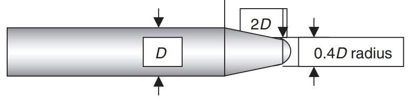 Figure 4 – Recommended tungsten electrode shape [1]
Manual TIG welding
Torch manipulation
The welder should attempt to maintain the shortest practicable arc length. In practice this is approximately equal to the electrode diameter. If the arc is too long penetration is decreased and the risk of lack of fusion defects is increased. Undercutting, poor bead shape and excessive bead widths may also be produced. Gas shielding may also be affected with entrainment of air into the shield gas giving oxide inclusions in the weld. The torch should be held normal to the weld but pointing forwards towards the direction of travel, at an angle of around 80°. When welding joints of unequal thickness the arc should be directed more towards the thicker side of the joint [1]
Filler rods
The filler rod, if used, should be fed into the leading edge of the weld pool with a slow, ‘dabbing’ action at an angle of 10–20° (Fig. 6.14). It should not be fed directly into the arc column as this tends to cause spatter and may accidentally contaminate the electrode. A steeper angle than 10–20° restricts the welder’s view of the weld pool. The tip of the filler rod should be held inside the gas shield while it is hot to prevent oxidation. As the component thickness increases the filler rod diameter increases, necessitating an increase in arc length. Bear in mind that too long an arc can cause oxide entrapment problems. A large diameter rod can also shield the material ahead of the weld pool from the cleaning action of the arc and this may also lead to oxide entrapment [1].
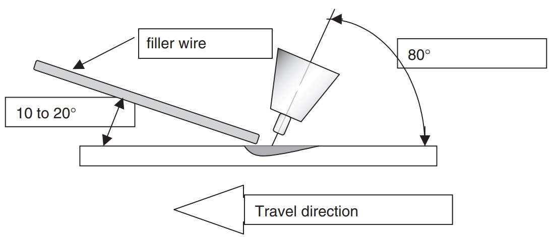 Figure 5 – Angle of torch and wire workpiece [1]
Welding completion
Very important is the controlled completion of welding. Abrupt shutdown of the welding current can lead to the formation of craters, sinks (elongated pores) and cracks in the last part of the weld pool. At the end of welding, it is necessary to gradually reduce the welding current and reduce the length of the arc as it attenuates, adding filler wire then, until the arc disappears.
Sources:

