How the microstructure of aluminium determines its properties
Any process for the fabrication of aluminium components determines not only the shape of the component, but also its microstructure. In turn, the microstructure determines the component’s attributes. It is very important to understand the interaction between processing chain, component shape, microstructure and the component’s properties is very important. Shaping, processing, joining and surface treatment are used for more than just giving a component a shape and a surface. In combination with casting parameters and thermal treatment, these processes allow us to control an alloy’s microstructure and achieve an optimal combination of properties for any given purpose.
Aluminum properties depend on its microstructure through features like grain size, the size, shape, and distribution of intermetallic phases, and the presence of precipitates, which affect mechanical properties, corrosion resistance, and electrical conductivity. Smaller grain sizes generally improve strength and hardness, while the nature of intermetallic phases and precipitates can significantly enhance strength through precipitation strengthening mechanisms, though sometimes at the cost of ductility. Alloying elements are used to control these microstructural features and thereby tailor the alloy’s properties.
Aluminium has a face-centred cubic lattice structure. This means the atoms are arranged so that they form the corners of a cube, with one atom in the centre of each face. The length of a side is about 0.4 nm. The atoms’ relative position in the lattice-arrangement will remain the same as long as there is no plastic deformation of the material. If the material is strained enough to cause plastic deformation, certain crystal planes slip in particular directions.
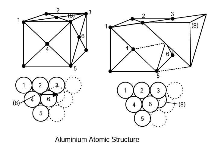 Figure 1
This figure presents a schematic illustration of an imperfect crystal structure. Certain planes of atoms end in the middle of the crystal. The line that forms along the edge of such an extra plane is called a dislocation. This edge or dislocation can move in particular atomic planes and directions. In that way, the dislocation moves along the slip plane, where new atoms continuously add momentum to its movement. Once it passes through an entire crystal, the crystal has sustained a plastic deformation.
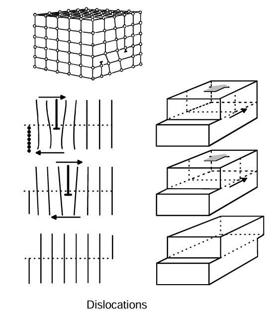 Figure 2
New dislocations are formed continually during plastic deformation. They start at one point and spread out in a ripple pattern, as illustrated in this figure. This facilitates continual plastic deformation. A metal’s strength and ductility can be explained on the basis of the migrations of the dislocations. By adding alloying elements, selecting process parameters for casting, mechanical working, heat treatment, joining and surface treatment, the microstructure can be “manipulated” to obtain the best possible combination of properties in the component.
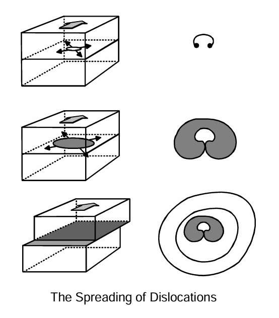 Figure 3
This figure illustrates a cold metal process called cold forging or impact extrusion. A cylindrical blank is cut from an extruded rod. When it is subjected to plastic deformation during the extrusion operation, dislocation sources will be formed inside each grain under the influence of external forces. The metal is strengthened by the deformations.
When sufficiently heavy deformations occur, it will reach a state of equilibrium between the formation of new dislocations and the annihilation of old ones. Thus the work hardening has reached the saturation point. The curve will flatten out as indicated in this figure. Heating will cause a component’s locked dislocations to melt together and disappear (annealing). We will obtain a “recovered” structure with a lower strength. It is possible to achieve the desired combination of strength and ductility through a controlled heating process called partial annealing or back annealing.
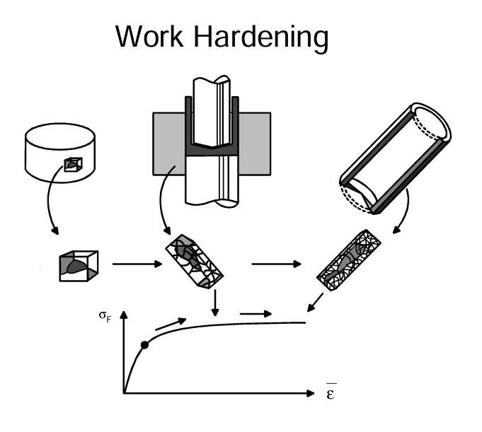 Figure 4
When atoms from another metal replace aluminium atoms in a crystal lattice, it is called, that the alloying element is in solid solution. Manganese and magnesium are typical examples of alloying elements in solution in aluminium. These atoms do not quite fit into the lattice, meaning the surrounding aluminium atoms are displaced slightly. This impedes the migration of dislocations through the crystal. The foreign atoms in solution add to the strength of the alloy.
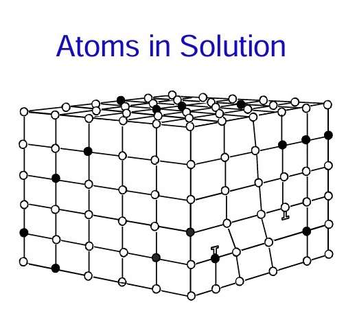 Figure 5
This figure shows particles (or thin bars) precipitated in the crystal lattice. Such particles are formed when alloying elements in solution are oversaturated (solution heat treatment) and precipitated (aging). For example, magnesium and silicon in solid solution are precipitated as an intermetallic compound in the form of needles or bars with a length of just a few tenths of a micrometre and a thickness of approximately 10 nm.
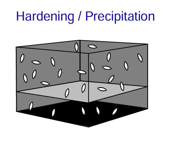 Figure 6
Solution heat-treatment can take place when the amount of the alloying elements in solution is reduced in proportion to temperature. We can see this from the phase diagram for the Al-Mg-Si system. The figure shows a cross-section of the diagram based on percentage weight of Mg-Si phase along the horizontal axis. In the “a-phase” area, Mg-Si phase are in solid solution. When an alloy containing approximately 1 per cent of Mg-Si particles is quenched rapidly from a temperature of roughly 570 °C to room temperature, the alloying elements will not have time to diffuse and form particles. The aluminium metal becomes oversaturated with magnesium and silicon in solid solution.
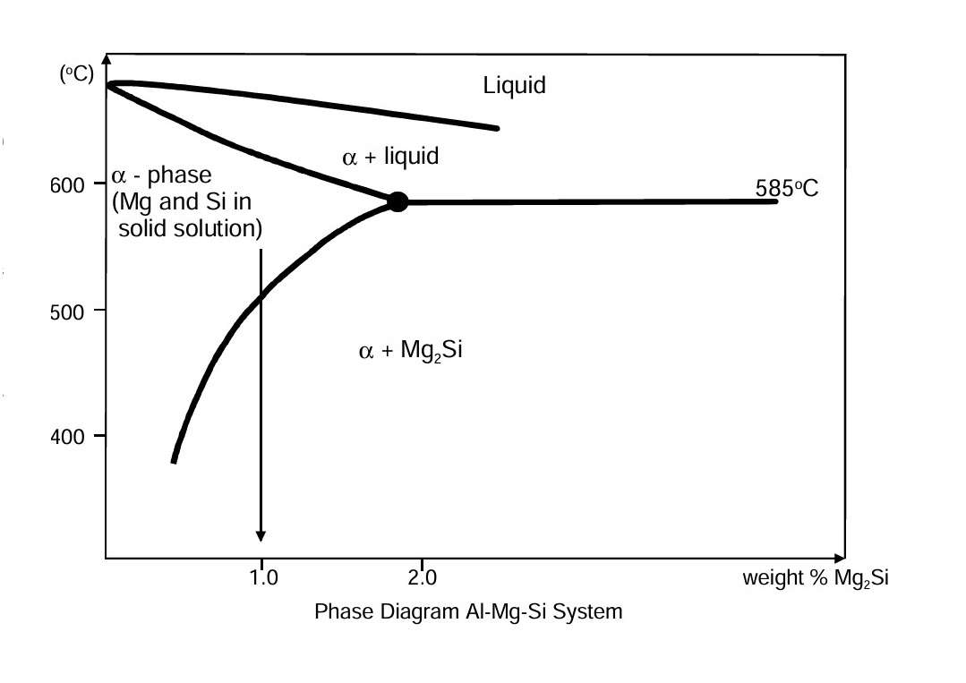 Figure 7
Artificial ageing involves heating the alloy to roughly 180 °C for a few hours. This will facilitate a controlled diffusion (migration) of the dissolved silicon and magnesium atoms towards the areas where the intermetallic Mg-Si phase begins to precipitate. At the same time, the surrounding crystal lattice will be slightly deformed because the precipitates do not quite fit into the structure. The hard needles precipitated, combined with the deformation of the surrounding lattice structure, mean that considerable external forces are required for a dislocation to pass through such areas. Consequently, the material’s flow stress increases significantly. If the alloy is kept at this high temperature for too long, it has been overaged, and the flow stress declines again.
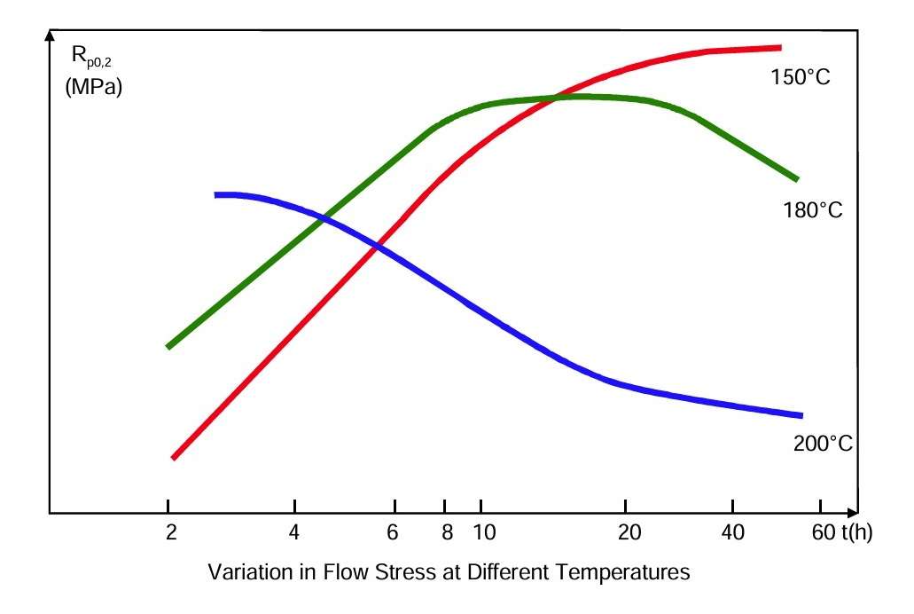 Figure 8
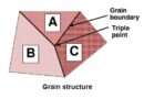
When the metal solidifies, the solidification process begins with small solid particles in the melt. These particles grow into crystals shaped like a dendrite. Each dendrite grows until it encounters neighbouring grains. The metal between the arms solidifies and the metal that solidifies last frequently has a different composition of alloying elements and impurities. This process forms an alloy’s cast structure.
Wrought alloys are hot rolled or extruded after being cast and homogenised. The cast structure will then be broken up and a new grain structure will be formed by recrystallization. Meanwhile, cast structure will be dissolved and distributed during homogenisation and the subsequent hot working process. The combination of cold deformation and heat-treatment will result in control of grain size, the structure of precipitated particles, dislocations, impurities and the alloying elements in solution.
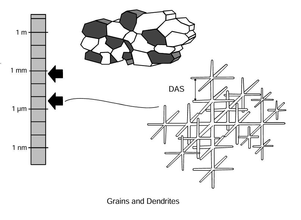 Figure 9
The source:
TALAT Lecture 2101.01 – Understanding Aluminium as a Material / Sigurd Støren – European Aluminium Association – 1994